
LNG optimum control reliquefaction system for recovering LNG low-temperature waste heat generated during LNG vaporization

A reliquefaction, cryogenic technology for gas/liquid distribution and storage, fixed-capacity gas storage tanks, container discharge methods, etc.

Active Publication Date: 2017-09-01
View PDF7 Cites 0 Cited by
  • Summary
  • Abstract
  • Description
  • Claims
  • Application Information

AI Technical Summary

Problems solved by technology

However, the above-mentioned prior art is only applicable to areas that require a large amount of LNG (specifically, NG gas as gaseous LNG), and it is difficult to introduce the above-mentioned system in an area with a small amount of LNG, and the above-mentioned system is basically a system that uses A system for gasification and utilization of liquid LNG

Method used


Image

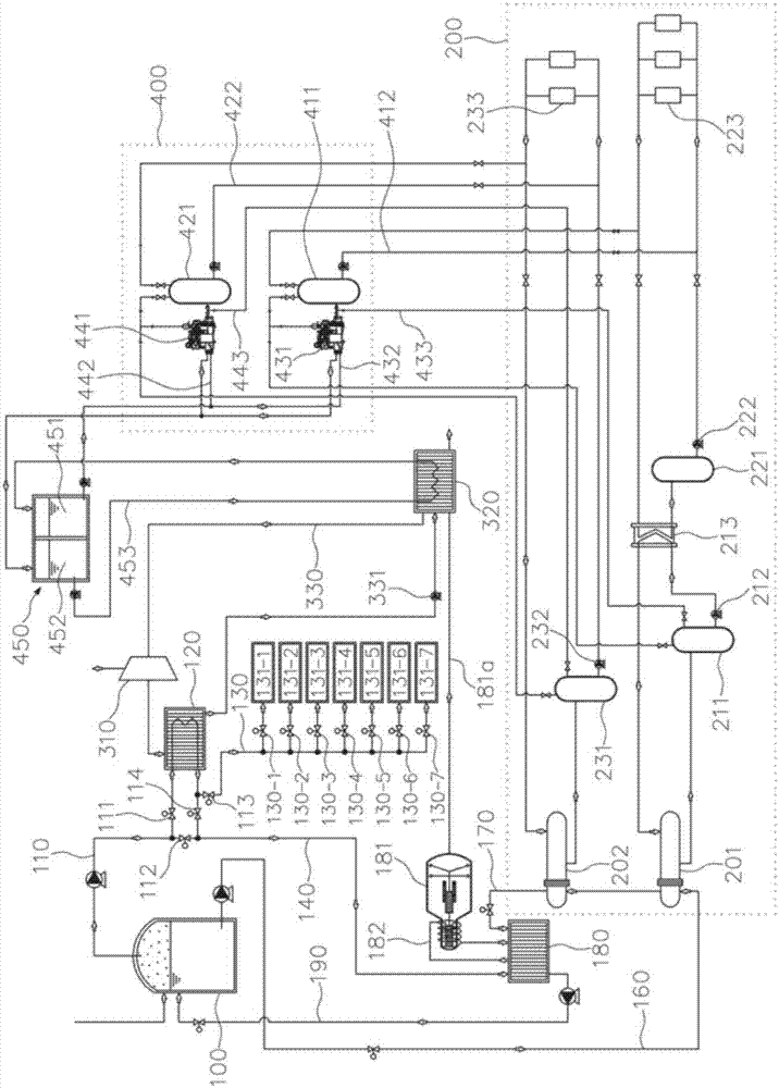
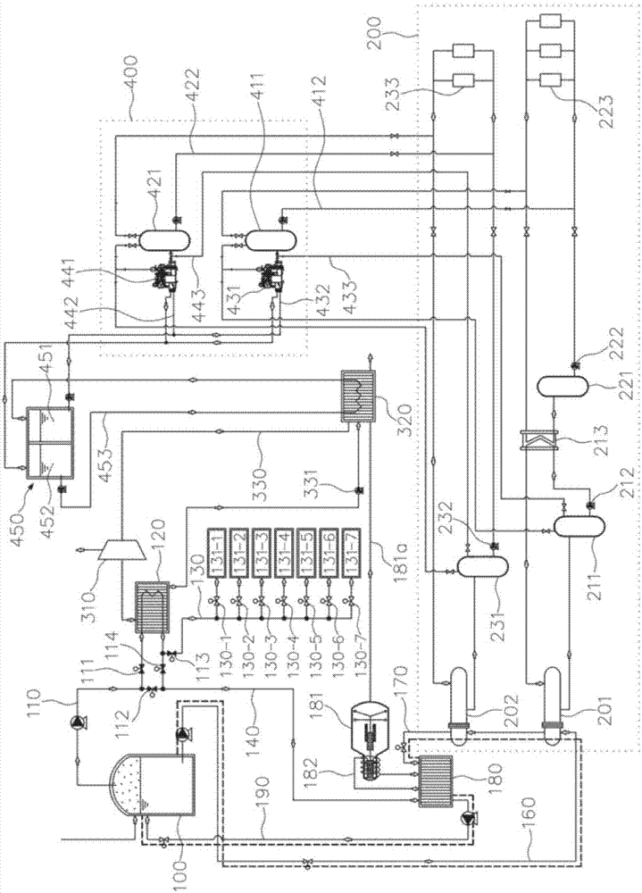
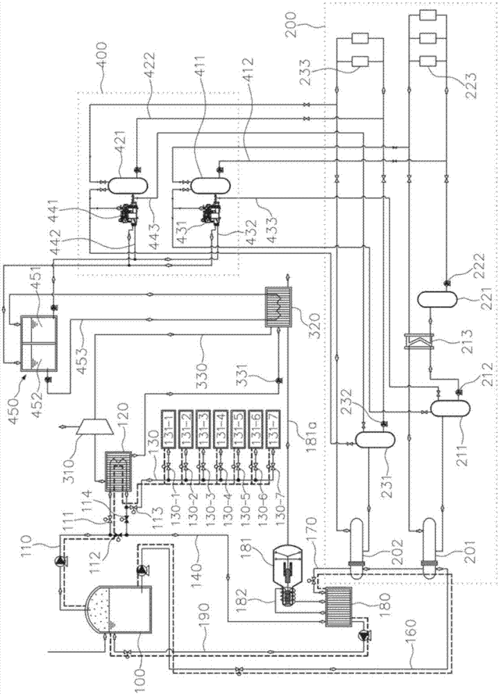
  • LNG optimum control reliquefaction system for recovering LNG low-temperature waste heat generated during LNG vaporization
  • LNG optimum control reliquefaction system for recovering LNG low-temperature waste heat generated during LNG vaporization
  • LNG optimum control reliquefaction system for recovering LNG low-temperature waste heat generated during LNG vaporization

Examples


Embodiment Construction

[0017] Hereinafter, embodiments of the present invention will be described in detail with reference to the accompanying drawings so that those having ordinary knowledge in the technical field to which the present invention pertains can easily implement. However, the present invention can be implemented in various ways and is not limited to the embodiments described here. In addition, in order to clarify the present invention, in the drawings, parts irrelevant to the description are omitted, and similar reference numerals are assigned to similar parts throughout the specification.

[0018] Throughout the specification, when it is described that a certain part "includes" a certain constituent element, if there is no specific contrary statement, it means that other constituent elements are not excluded, but may also include other constituent elements.

[0019] The specific kinds of refrigerants above and below are just one example, and different kinds of refrigerants can be used ...


PUM


Abstract

The invention relates to an LNG optimum control reliquefaction system for recovering LNG low-temperature waste heat generated during LNG vaporization. The present invention is configured to: supply gaseous LNG to a gaseous LNG consumer while allowing liquid LNG to discharge cold energy through a heat exchanger for a load of a cold energy supply unit for a warehouse, so as to supply a sufficient amount of the gaseous LNG within an LNG storage tank, thereby increasing the temperature of or vaporizing the liquid LNG; allow the LNG with an elevated temperature or vaporized to be supplied to a gaseous LNG consumer supply line, thereby expanding the cold energy use and dissemination of the LNG; and optimally control and reliquefy the flux of the liquid LNG and gaseous LNG, thereby economically recovering the low-temperature waste heat of the LNG generated during LNG vaporization.

Description

technical field [0001] The invention relates to an LNG optimum control reliquefaction system for recovering LNG low-temperature waste heat produced in the LNG gasification process. Background technique [0002] At present, LNG is used as green energy, and in order to use LNG, LNG bases with multiple LNG liquefied gas storage tanks are built on the coast. [0003] The LNG liquefied gas storage tank stores liquefied LNG gas, and in order to supply an appropriate amount of LNG gas to the required place, the liquefied gas is vaporized and then supplied to the required place (piping of city gas, etc.). [0004] In order to gasify LNG liquefied gas, gasifiers are generally used. Gasifiers are roughly divided into open-frame gasifiers and combustion-type gasifiers. The most economical open-frame gasifiers receive water (sea water) from the outside. By performing heat exchange, the liquid LNG undergoes a phase transition and is output in a gaseous state at normal temperature. [0...

Claims


Application Information

Patent Timeline
IPC IPC(8): F17C7/02F17C7/04F17C13/00
CPCF17C9/00F17C9/02F17C13/00F17C13/04F17C7/02F17C7/04F17C2221/033
Inventor 杨元敦李成春李东建李大镇
Learn More