Shearing crusher cutter and crushing shaft device

A crusher and shearing technology, which is applied in the field of shearing crusher crushing shaft device, can solve the problems of crushing shaft damage, motor life reduction, motor burnout, etc., to achieve the effect of reducing resistance and improving life

Pending Publication Date: 2017-09-05
ZHAOQING HI TECH ZONE GUOZHUAN TECH CO LTD
View PDF16 Cites 4 Cited by
  • Summary
  • Abstract
  • Description
  • Claims
  • Application Information

AI Technical Summary

Problems solved by technology

[0003] However, when the existing crushing tool breaks a relatively hard block to be broken, the crushing tool is easy to slip; or when a large block is to be broken, the tool cannot completely cut or crush it at one time, resulting in easy material ja

Method used


Image

  • Shearing crusher cutter and crushing shaft device
  • Shearing crusher cutter and crushing shaft device
  • Shearing crusher cutter and crushing shaft device

Examples


Embodiment 1

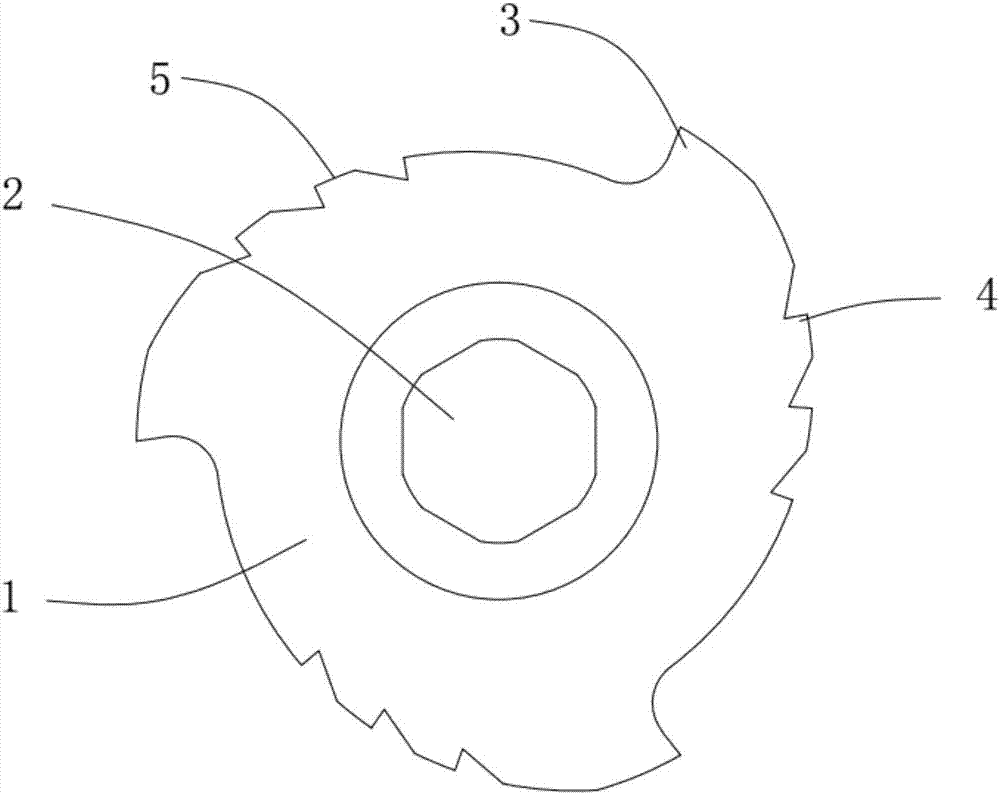
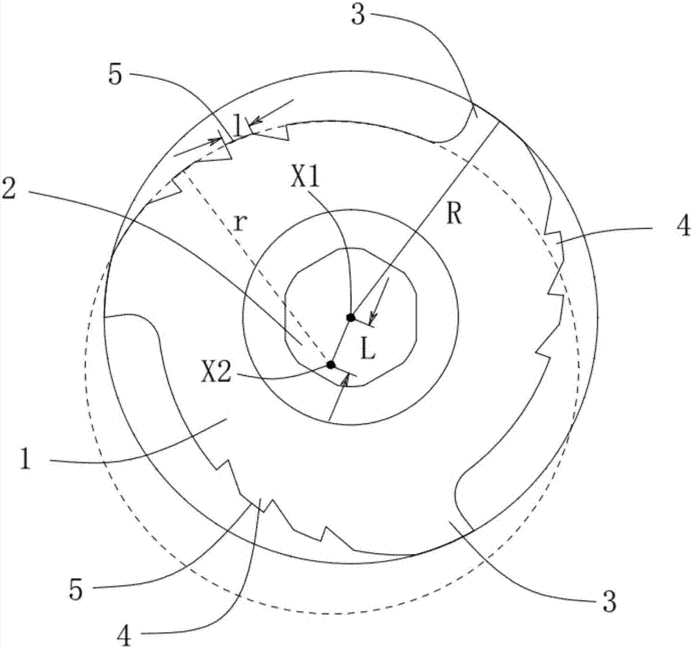
[0036] Such as Figure 1-2 As shown, the cutter of the present invention includes a cutter body 1 and a cutter shaft installation hole 2 arranged in the center of the cutter body 1 . The outer periphery of the cutter body 1 is provided with several main blades 3, and the several main blades 3 are evenly distributed on the outer periphery of the cutter body 1 with the cutter shaft mounting hole 2 as the center of circle;

[0037] It also includes several groups of auxiliary blades 4, each group of auxiliary blades 4 is arranged between two adjacent main blades 3, and each group of auxiliary blades 4 is located on different arc curves;

[0038] The distance between the main blade 3 and the shaft mounting hole 2 is greater than the distance between the secondary blade 4 and the shaft mounting hole 2 .

[0039] Several groups of secondary blades 4 are added to increase the cutting length of the shearing edge and improve the utilization rate of the cutter. When cutting bulk mater...

Embodiment 2

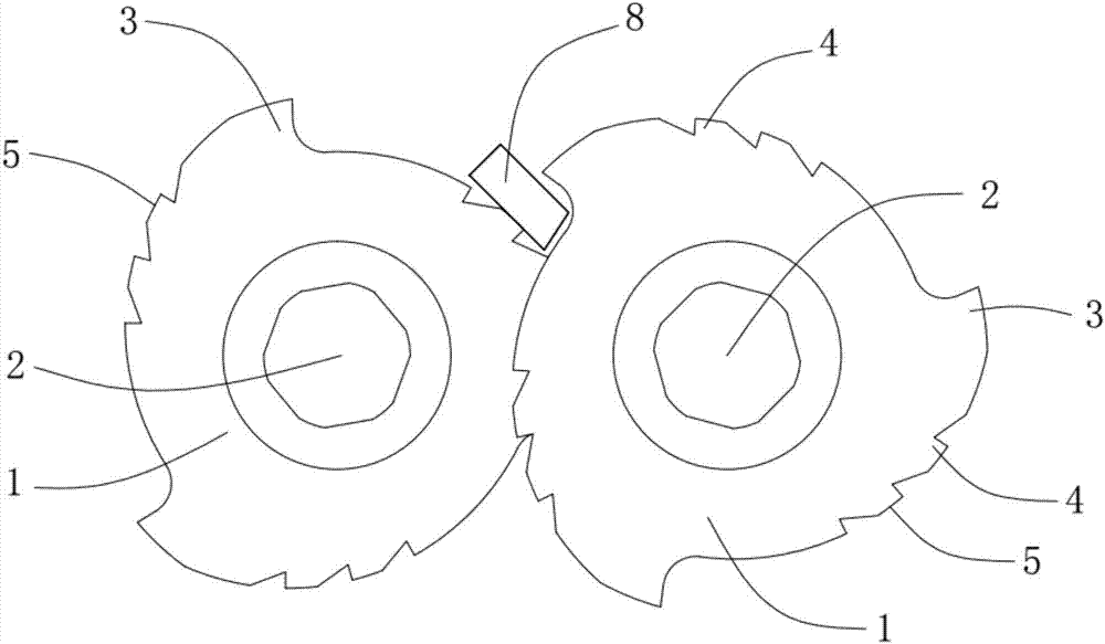
[0052] Such as Figure 3-4 Shown is the shearing crusher crushing shaft device applied to the shearing crusher cutter, which includes a cutter shaft and the shearing crusher cutter installed on the cutter shaft in the above-mentioned manner, the shearing crushing There are at least two machine knives, and a spacer 7 is arranged between the knife shaft and the shear crusher knives.

[0053] The cutter shaft includes a first cutter shaft 6 and a second cutter shaft 9, and at least two shearing crusher cutters are respectively arranged on the first cutter shaft 6 and the second cutter shaft 9, and at least two shearing crushers There is a gap between the knives;

[0054] The cutter of the shearing crusher on the first cutter shaft 6 and the cutter of the shearing crusher on the second cutter shaft 9 are mutually staggered during cooperation;

[0055] The shearing crusher cutter on the first cutter shaft 6 is opposite to the tooth mouth of the shearing crusher cutter 9 on the se...


PUM

PropertyMeasurementUnit
Lengthaaaaaaaaaa

Abstract

The invention belongs to the technical field of fine crushing, and in particular, discloses a shearing crusher cutter and a crushing shaft device of a shearing crusher applying the cutter. The cutter comprises a cutter body, and a cutter shaft mounting hole formed in the center of the cutter body; and multiple main edges are arranged at the outer periphery of the cutter body, and are uniformly distributed on the outer peripheral edge of the cutter body with the cutter shaft mounting hole as the circle center. The cutter further comprises multiple sets of secondary edges; each set of secondary edges is arranged between two adjacent main edges; and the distances from the main edges to the cutter shaft mounting hole are larger than the distances from the secondary edges to the cutter shaft mounting hole. The crushing shaft device comprises a cutter shaft, and cutters mounted on the cutter shaft; at least two cutters are provided; and spacing sleeves are arranged between the cutter shaft and the cutters. The cutter can fully crush materials to be crushed to improve the crushing efficiency, and relatively prolongs the service life of a crushing shaft and a motor.

Description

technical field [0001] The invention belongs to the technical field of fine crushing, and in particular relates to a cutter of a shearing crusher and a crushing shaft device of a shearing crusher using the cutter. Background technique [0002] At present, the general material crushing device uses a motor to drive the rotation of the crushing shaft installed in the crushing box, and the cutter installed on the crushing shaft can rotate the material for cutting and crushing. Normally, the crusher cutter can break the hard block to be broken into smaller size, when the block to be crushed is introduced between two relatively moving crushing knives, the movement of the cutter makes the block to be crushed crushed. [0003] However, when the existing crushing tool breaks a relatively hard block to be broken, the crushing tool is easy to slip; or when a large block is to be broken, the tool cannot completely cut or crush it at one time, resulting in easy material jam. And the cru...

Claims


Application Information

Patent Timeline
IPC IPC(8): B02C18/18B02C18/16
CPCB02C18/16B02C18/18
Inventor 罗志勤
Owner ZHAOQING HI TECH ZONE GUOZHUAN TECH CO LTD
Why Eureka
Try Eureka