Photovoltaic board group mobile cart

A technology for moving carts and photovoltaic panel groups, which is applied to trolleys, motor vehicles, multi-axis carts, etc., can solve the problems of photovoltaic panel group bumping, time-consuming and laborious handling, etc., and achieves stability, convenience, and transportation. Effect

Pending Publication Date: 2017-09-05
CHENGDU ZHENZHONG ELECTRIC
View PDF10 Cites 0 Cited by
  • Summary
  • Abstract
  • Description
  • Claims
  • Application Information

AI Technical Summary

Problems solved by technology

[0003] The purpose of the present invention is to provide a mobile trolley for photovoltaic panel groups, which solves the problem that traditional photovoltaic panel groups are often transported by manpower, and a little carelessness will cause impacts on photovoltaic panel groups. At the same time, it also solves the problem of handling Time-consuming and labor-intensive problems in the process

Method used


Image

  • Photovoltaic board group mobile cart
  • Photovoltaic board group mobile cart
  • Photovoltaic board group mobile cart

Examples


Embodiment 1

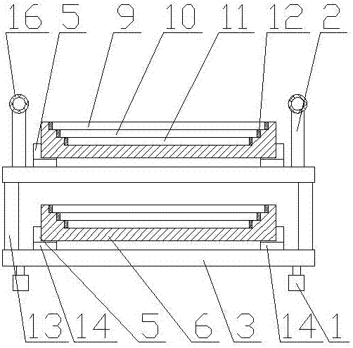
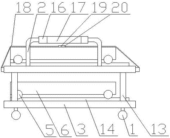
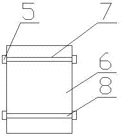
[0035] Such as figure 1 , 2 As shown in and 3, the mobile trolley of the photovoltaic panel group includes a placement device, universal wheels 1 and handrails 2, and the placement device includes a storage board 3, guide rails, pulleys 5 and a photovoltaic panel group placement tank 6, and the storage board 3 is equipped with There is a shaft groove 7 on the bottom surface of the photovoltaic panel group placement tank 6, and a shaft 8 is installed in the shaft slot 7. The pulley 5 is installed at both ends of the shaft 8. The pulley 5 cooperates with the guide rail, and the photovoltaic panel group placement tank body 6 is slidably connected with the storage board 3; the photovoltaic panel group placement groove body 6 is provided with a first photovoltaic panel groove 9, wherein a second photovoltaic panel groove 10 is opened on the bottom of the first photovoltaic panel groove 9, and the second There is a third photovoltaic panel groove 11 on the groove bottom of the phot...

Embodiment 2

[0037] Such as figure 1 , 2 As shown in and 3, compared with embodiment 1, this embodiment optimizes the guide rail, which is composed of two mutually parallel rails 14; there are two groups of rotating shaft grooves 7, and they are arranged in parallel on the bottom surface of the photovoltaic panel group placement groove body 6; Each track 14 is provided with two pulleys 5, and the distance between the two pulleys 5 is less than the length of the track 14. In this embodiment, the two tracks 14 can more stably support the photovoltaic panel group placement tank 6, and Each track 14 is provided with two pulleys 5 to further stabilize the movement of the photovoltaic panel group placement tank 6 on the track 14 .

Embodiment 3

[0039] Such as figure 2 As shown, compared with Embodiment 2, this embodiment optimizes the guide rails. Along the pushing direction of the photovoltaic panel group placement tank 6, the ends of the rails 14 are all provided with stoppers 15. In this embodiment, the stoppers 15 It can prevent the installation tank body 6 of the photovoltaic panel group from being pushed down from the track 14 .


PUM


Abstract

The invention discloses a photovoltaic board group mobile cart. The photovoltaic board group mobile cart comprises a mounting device, a universal wheel and a handrail. The mounting device comprises a placing plate, a guide rail, a pulley and a photovoltaic board group mounting groove body. The guide rail is mounted on the placing plate; the bottom surface of the photovoltaic board group mounting groove body is provided with a rotating shaft groove; a rotating shaft is arranged in the rotating shaft groove; the pulley is mounted on both ends of the rotating shaft; the pulley and the guide rail are cooperated with each other; the photovoltaic board group mounting groove body is slidably connected with the placing plate; the mounting device has two or more groups which are fixed in a layering mode through a support frame respectively; the universal wheel is fixedly connected on the lower bottom surface of the placing plate at the lowest layer; the universal wheel has three or more; on the placing plate at the topmost layer, two sides of the guide rail are respectively provided with the handrail. The photovoltaic board group mobile cart has the advantages of being convenient for the transportation use for using personnel; being capable of conveying photovoltaic boards with different sizes.

Description

technical field [0001] The invention relates to a mobile trolley, in particular to a photovoltaic panel group mobile trolley. Background technique [0002] At present, the photovoltaic panel group is often carried by manpower during the handling process, and the manual handling will not only cause time-consuming and laborious work, but also cause the photovoltaic panel group to be bumped if the staff is slightly careless during the handling, thus causing the photovoltaic panel group to break. And other problems affect the use of photovoltaic panels. Contents of the invention [0003] The purpose of the present invention is to provide a mobile trolley for photovoltaic panel groups, which solves the problem that traditional photovoltaic panel groups are often transported by manpower, and a little carelessness will cause impacts on photovoltaic panel groups. At the same time, it also solves the problem of handling time-consuming problems in the process. [0004] In orde...

Claims


Application Information

Patent Timeline
Patent Type & Authority Applications(China)
IPC IPC(8): B62B3/04B62B5/06
CPCB62B3/04B62B5/06B62B2203/74
Inventor 王刚胡国波聂海涛
Owner CHENGDU ZHENZHONG ELECTRIC
Why Eureka
Try Eureka