Jet pipe servo valve capable of adjusting axis position of nozzle and adjustment method

A technology of jet tube and servo valve, which is applied in the field of jet tube servo valve and debugging, can solve the problems of increasing the leakage rate of jet tube servo valve, lack of awareness of centering detection of jet tube servo valve, etc., to ensure centering installation and deviation distance The effect of reducing and reducing the flow leakage rate

Inactive Publication Date: 2017-09-05
TONGJI UNIV
View PDF6 Cites 11 Cited by
  • Summary
  • Abstract
  • Description
  • Claims
  • Application Information

AI Technical Summary

Problems solved by technology

[0007] At present, the jet tube servo valve lacks strict alignment detection awareness during installation, and in fact, installation errors will greatly increase the leakage rate of the jet tube servo valve. This patent proposes a detection method to ensure that the jet tube servo valve The axis of the nozzle is located in the plane of the axis of the two jet receiving holes, so as to improve the flow utilization rate of the jet tube servo valve and reduce internal leakage

Method used


Image

  • Jet pipe servo valve capable of adjusting axis position of nozzle and adjustment method
  • Jet pipe servo valve capable of adjusting axis position of nozzle and adjustment method
  • Jet pipe servo valve capable of adjusting axis position of nozzle and adjustment method

Examples


Embodiment

[0040] Example:

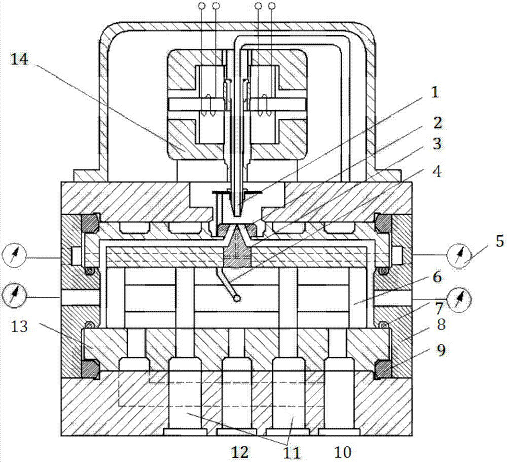
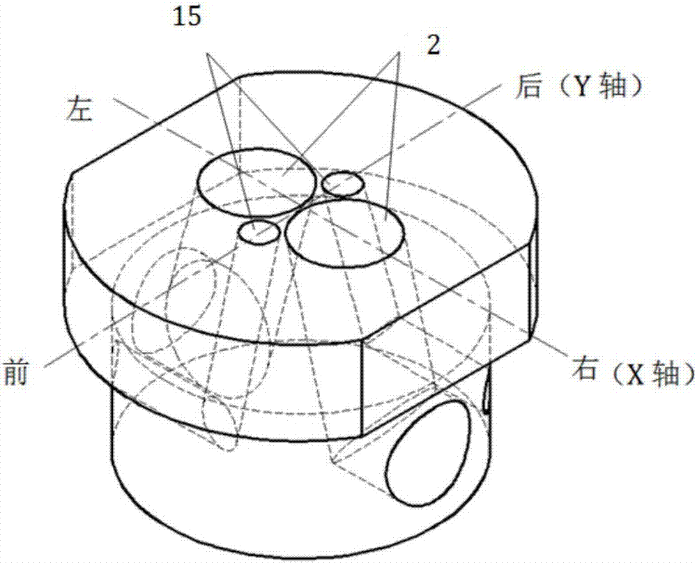
[0041] Such as figure 1 As shown, the jet pipe servo valve is composed of a torque motor 14 , a jet nozzle 1 , a jet receiving seat 3 , a feedback rod 4 , a valve sleeve 13 and a valve core 6 . The two jet receiving holes 2 on the jet receiving seat 3 are respectively connected with the left and right chambers of the valve core 6, the jet receiving seat 3 is inserted on the valve sleeve 13, the valve core 6 is placed in the valve sleeve 13, and the upper end of the feedback rod 4 is connected to the jet nozzle. 1, and the lower end is connected with the main spool 6. After the control current is applied, the jet nozzle 1 is shifted under the drive of the torque motor 14, the energy received by the two jet receiving holes 2 of the jet receiving seat 3 is no longer the same, and a pressure difference is formed to push the main valve core 6 to move, and the main valve core 6 The jet tube is dragged by the feedback rod 4 to move in reverse, and the main valve c...


PUM


Abstract

The invention discloses a jet pipe servo valve capable of adjusting axis position of a nozzle. The jet pipe servo valve comprises a valve body, a jet nozzle which is arranged on the upper part of the valve body is controlled through a torque motor, adjustment end covers which are arranged on two ends of the valve body, a pressure detection device, a valve bush arranged in the valve body, a valve core arranged in the valve bush and a receiving base which is embedded in the valve core and is used for receiving a flow beam of nozzle jet flow, wherein two jet flow receiving holes are formed in the jet flow receiving base; the two jet flow receiving holes separately communicate with cavities at two ends of the valve core in the valve bush through receiving slot holes formed in the wall of the valve bush; the pressure detection device comprises two pressure detection holes formed in the jet flow receiving base and first pressure sensors arranged on the end covers; and the two pressure detection holes are separately connected with the pressure sensors through detection slot holes formed in the wall of the valve bush. Compared with the prior art, the jet pipe servo valve has the advantages that the axis position of the nozzle can be adjusted; the nozzle is arranged with the axis being centered front and back, so that a leakage rate in the jet pipe servo valve is lowered; and the like.

Description

technical field [0001] The invention relates to the technical field of mechanical parts and transmission devices of mechanical engineering and fluid control, in particular to a jet tube servo valve capable of adjusting the axial position of a nozzle and a debugging method. Background technique [0002] The jet tube servo valve appeared in the 1950s. After decades of development, the jet tube servo valve has been widely used in civil and military aerospace equipment due to its advantages of fast response, strong anti-pollution ability, and high reliability. In the system, but due to its structure and the processing and assembly limitations of parts at all levels, its internal leakage is relatively large. [0003] Foreign jet pipe servo valve manufacturers mainly include MOOG, MTS, HONEYWELL, etc. During the Second World War, the German Askania company first invented the jet tube servo valve. [0004] In terms of structure, after the emergence of single-stage jet tube servo ...

Claims


Application Information

Patent Timeline
Patent Type & Authority Applications(China)
IPC IPC(8): F15B13/02F15B19/00
CPCF15B13/02F15B19/002
Inventor 訚耀保夏飞燕李长明
Owner TONGJI UNIV
Why Eureka
Try Eureka