
Mold hydraulic testing machine box

A testing machine and hydraulic technology, applied in fluid pressure actuation system testing, mechanical equipment, fluid pressure actuation devices, etc., can solve problems such as impurities not being cleaned up, economic loss, failure to continue mold testing, etc.

Inactive Publication Date: 2017-09-05
HUANGSHI HONGXING PLASTIC MOLD
View PDF0 Cites 0 Cited by
  • Summary
  • Abstract
  • Description
  • Claims
  • Application Information

AI Technical Summary

Problems solved by technology

[0003] 1. When the mold is tested on the machine, if the mold has the following problems: there is a defect in the ejector mechanism, such as impurities that have not been cleaned up during the mold assembly, resulting in problems with the ejection, and it is impossible to continue the mold trial; the rubber in the mold cylinder The quality of the ring is not good enough, resulting in oil leakage in the mold cylinder; when the top block of the mold is loose or dangerous, it is necessary to remove the mold from the machine and re-adjust and process the mold, which will cause trouble and damage caused by rework The loss is very huge, especially for some large molds, such as molds for bumpers, dashboards, door panels, sub-dashboard molds, etc.
[0004] 2. After the mold is tested on the machine, it is easy to ship after several proofings and customer acceptance. For some potential problems of the mold, it can only be eliminated after the customer purchases the mold and goes back to produce a certain number of products or use it for a certain period of time. It is found that mold manufacturers often need to send technicians to carry out maintenance, which also brings delays in production time to customers, resulting in economic losses, and also creates a bad impression on customers
[0005] In order to solve the above-mentioned problems existing in the inspection of injection molding machines, the applicant has developed a mold hydraulic testing machine, which is specially used for testing the hydraulic system and ejection system of the mold. However, during the research and development process, the mold hydraulic testing machine still exists Some shortcomings: because the test machine installs all the required components together, such as integrating the fuel tank, oil pump, motor, control system, cooling system, etc. Side panels, but since motors, oil pumps, electric boxes and other components will generate a lot of heat during work, this requires good heat dissipation
In this way, if the structure of a conventional machine is adopted, it cannot meet the normal heat dissipation requirements of the testing machine.

Method used


Image

  • Mold hydraulic testing machine box
  • Mold hydraulic testing machine box

Examples


Embodiment Construction

[0015] Below in conjunction with the accompanying drawings, the mold hydraulic test case body of the present invention will be further described.

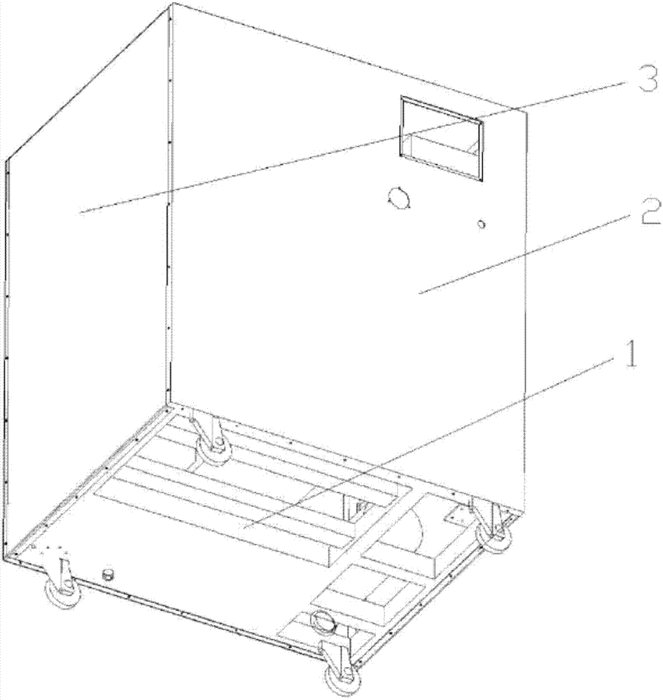
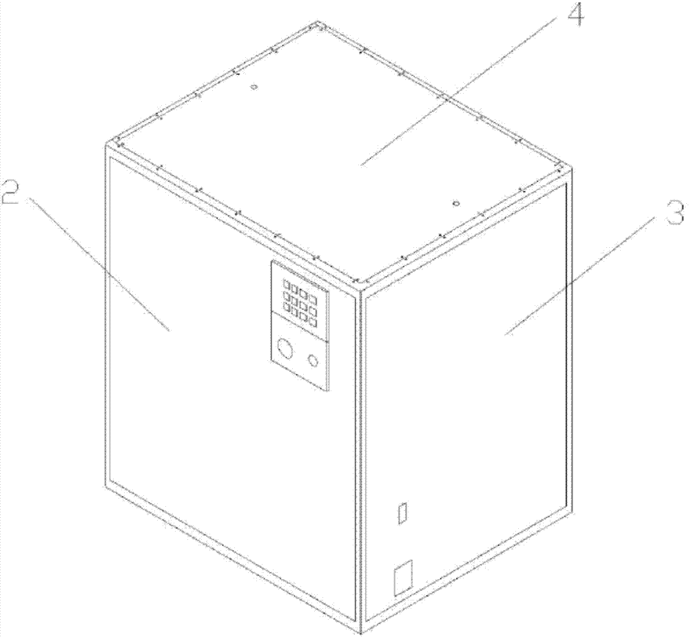
[0016] like figure 1 , figure 2 As shown, the mold hydraulic test box body of the present invention includes a frame 1 for installing the components of the testing machine.

[0017] The front and rear door panels 2 , the left and right side panels 3 and the top panel 4 are all detachably connected to the frame 1 .

[0018] The detachable connection is a bolt connection.


PUM


Abstract

The invention discloses a mold hydraulic testing machine box body, which comprises a frame (1) for installing components of the testing machine, and the frame (1) is also provided with front and rear door panels (2), left and right side panels (3) and The top plate (4), the front and rear door panels (2), the left and right side panels (3) and the top plate (4) are all detachably connected with the frame (1), and the detachable connection is a bolt connection. The mold hydraulic test case body can meet the normal heat dissipation requirements.

Description

technical field [0001] The invention relates to the technical field of testing equipment, in particular to a mold hydraulic testing box body. Background technique [0002] At present, mold manufacturers, especially injection mold manufacturers, can only test molds with oil cylinders by testing the mold on the injection molding machine, and there are a series of shortcomings in the inspection on the injection molding machine: [0003] 1. When the mold is tested on the machine, if the mold has the following problems: the ejection mechanism has defects, such as impurities that are not cleaned up during mold assembly, resulting in problems with ejection, and the mold cannot continue to be tested; the rubber in the mold cylinder The quality of the ring is not good enough, resulting in oil leakage in the mold cylinder; when the top block of the mold is loose or dangerous, it is necessary to unload the mold, and adjust and deal with the mold again. The loss is very huge, especiall...

Claims


Application Information

Patent Timeline
IPC IPC(8): F15B21/00F15B21/04F15B19/00
CPCF15B21/00F15B19/00F15B21/042
Inventor 张红平刘守华邹昌明邓坤东程晓华
Owner HUANGSHI HONGXING PLASTIC MOLD
Learn More