Spiral type dryer

A dryer and spiral technology, applied in the direction of progressive dryers, dryers, drying chambers/containers, etc., can solve the problems of short drying time and large waste of space for materials, and achieve long residence time and large waste of space , high efficiency effect

Pending Publication Date: 2017-09-05
XIANGZHOU COUNTY INST OF SCI & TECHN INFORMATION
View PDF9 Cites 2 Cited by
  • Summary
  • Abstract
  • Description
  • Claims
  • Application Information

AI Technical Summary

Problems solved by technology

[0005] The invention provides a space-saving, high-efficiency spiral dryer, which solves the problems of large waste of space and short drying time of materials in traditional similar devices

Method used


Image

  • Spiral type dryer
  • Spiral type dryer

Examples


Embodiment Construction

[0013] The present invention will be further described below in conjunction with specific drawings and embodiments.

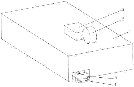
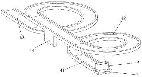
[0014] Such as Figure 1-2 As shown, the present invention mainly includes a drying chamber 1, a fan 2 for blowing air, an electric heating box 3 for generating heat, a trolley 5 for transporting materials, and a material track 4 for the movement of the trolley, and the fan 2 is connected to an electric heater. The box 3 is installed on the top of the drying chamber 1, and the trolley 5 is placed on the material rail 4. The material rail 4 is composed of an inlet rail 41, a spiral rail 42, an outlet rail 43, and a support 44. The inlet rail 41 is exposed from the entrance of the drying chamber 1. An exit rail 43 emerges from the exit of the drying chamber 1 .

[0015] When working, start the fan 2 and the electric heating box 3 to deliver dry hot air to the drying chamber 1, place the trolley on the inlet track 41 of the material track 4, load the material on ...


PUM


Abstract

The invention discloses a spiral type dryer. The spiral type dryer comprises a fan which is connected with an electric heating box and is mounted on the top of a drying room; a trolley is mounted on a material rail; the material rail consists of an inlet rail, a spiral rail, an outlet rail and a supporting part; the inlet rail is exposed from an inlet of the drying room; the outlet rail is exposed from an outlet of the drying room; the spiral rail is connected with the inlet rail and the outlet rail; and the supporting part is fixedly mounted below the spiral rail. The spiral type dryer solves the problems that a conventional dryer greatly wastes space and is short in material drying time; the spiral device has the characteristics of small floor space and a long rail, so that materials are kept for a long time in the drying room, materials which enter the drying room once are many; and the trolley can automatically move, so that continuous drying operation can be guaranteed, and therefore, the spiral type dryer has the advantages of high efficiency, high structural stability and strong maneuverability.

Description

technical field [0001] The invention belongs to the technical field of drying equipment in chemical plants, and relates to a spiral dryer. Background technique [0002] At present, chemical plants need to dry raw materials or products when producing products, or need to carry out drying processes in the manufacturing process, such as barium sulfate and barite manufacturing processes. Dryers are widely used in the food industry, tobacco industry or pharmaceutical industry. The current dryer converts electric energy or fossil energy into heat energy, uses heat energy to heat water into water vapor, and then separates water vapor from the object to be dried, and the material is loaded on a straight transport track to achieve the purpose of continuous work , but this kind of dryer wastes a lot of space in the drying room, and in order to ensure the time for the materials to stay in the drying room, the length of the drying room and the track have to be increased, while increasi...

Claims


Application Information

Patent Timeline
Patent Type & Authority Applications(China)
IPC IPC(8): F26B15/26F26B21/00F26B25/08
CPCF26B15/26F26B21/001F26B25/08
Inventor 李玉秋韦颖婷韦倩梅
Owner XIANGZHOU COUNTY INST OF SCI & TECHN INFORMATION
Why Eureka
Try Eureka