Annular strain gauge for hole drilling method

A technology of strain gauge and drilling method, which is applied in the field of ring strain gauge, can solve the problems of increasing test difficulty and error by drilling method, and achieve the effect of reducing the difficulty of patching and improving the test accuracy

Pending Publication Date: 2017-09-05
CHANGZHOU UNIV
View PDF6 Cites 0 Cited by
  • Summary
  • Abstract
  • Description
  • Claims
  • Application Information

AI Technical Summary

Problems solved by technology

[0004] In order to solve the defects in the prior art that the drilling method using the traditional strain gauge increases the diff

Method used


Image

  • Annular strain gauge for hole drilling method
  • Annular strain gauge for hole drilling method

Examples


Embodiment Construction

[0014] The present invention will be further described below in conjunction with the accompanying drawings and embodiments.

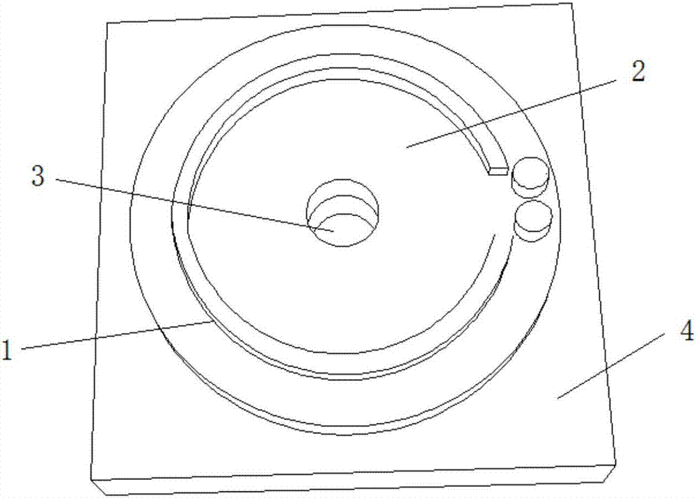
[0015] Such as figure 2 As shown, a ring-type strain gauge used for the drilling method includes a resistance wire 1 and an insulating base 2. The resistance wire 1 is arranged on the insulating base 2 in a ring-wound manner. The center of the resistance wire 1 is reserved for Drill marks.

[0016] The present invention is a ring-type strain gauge used in the drilling method. The working principle is: the ring-type strain gauge is pasted on the base material 4, and the insulating base 2 made of epoxy phenolic and other materials is used as the base material 4 and the resistance wire 1, drill a small hole 3 at the drilling mark reserved at the center of the resistance wire 1 during the test for strain relief. To sum up, the present invention is free to mount, can effectively reduce the testing difficulty of the drilling method using traditional strain...


PUM


Abstract

The invention discloses an annular strain gauge for a hole drilling method, and belongs to the technical field of civil and mechanical engineering. The annular strain gauge comprises resistance wires and an insulating base, the resistance wires are arranged on the insulating base in a circularly winding mode, and a drilling marker is reserved in the circle center of the resistance wires. By means of the annular strain gauge, free surface mounting can be achieved, testing difficulty of a hole drilling method by means of traditional strain gauges can be effectively reduced, and an error caused by surface mounting deviation can be eliminated.

Description

technical field [0001] The invention belongs to the technical field of civil engineering and mechanical engineering, and relates to a drilling method for detecting component internal stress or residual stress, in particular to a ring-type strain gauge used for the drilling method. Background technique [0002] At present, in the field of civil and mechanical engineering, the drilling method is a very effective micro-damage detection method for testing the internal stress or residual stress of components. When testing, stick the strain gauge first, and then drill holes to release the stress locally. The local release of the stress leads to the local release of the strain around the small hole. Using the strain gauge to measure some indicators of this local release, the initial stress can be deduced. [0003] At present, the drilling method uses traditional strain gauges, and the schematic diagram of the process is as follows: figure 1 shown. Since the small hole 3 and the ...

Claims


Application Information

Patent Timeline
IPC IPC(8): G01L1/22
CPCG01L1/22G01L1/2206
Inventor 杨兆王力威王同国卫志勇
Owner CHANGZHOU UNIV
Why Eureka
Try Eureka