Medical detection sample filling device

A filling device and sample technology, which is applied in the field of medical devices, can solve the problems of difficult precise control of the number of bubbles, movement direction and speed, and inaccurate filling volume of whole blood samples, so as to achieve the effect of ensuring work efficiency

Active Publication Date: 2017-09-05
马鞍山岩东精密仪器科技有限公司
View PDF5 Cites 0 Cited by
  • Summary
  • Abstract
  • Description
  • Claims
  • Application Information

AI Technical Summary

Problems solved by technology

[0003] The traditional device has the following problems: 1. After the sample is filled, the diluent on the outer wall of the sampling needle will continue to be added according to the dilution ratio. At this time, although the syringe pump has stopped, the diluent flowing downward at a high speed Negative pressure is formed at the lower port of the sampling needle, and part of the remaining whole blood sample inside the sampling needle will be sucked away, and filled into the measuring cup together with the diluent, resulting in inaccurate filling volume of the whole blood sample; 2. The whole blood sample and diluent inside the measuring cup also need to be mixed. Usually, the air flow enters the bottom of the measuring cup. The effect of mixing the whole blood sample and the diluent, but it is difficult to accurately control the number, direction and speed of the bubbles formed, and if the bubbles burst, it will affect the shape and volume of various blood cells in the whole blood sample

Method used


Image

  • Medical detection sample filling device
  • Medical detection sample filling device
  • Medical detection sample filling device

Examples


Embodiment Construction

[0023] The technical solutions in the embodiments of the present invention will be clearly and completely described below in conjunction with the accompanying drawings in the embodiments of the present invention. Obviously, the described embodiments are only a part of the embodiments of the present invention, rather than all the embodiments. Based on the embodiments of the present invention, all other embodiments obtained by those of ordinary skill in the art without creative work shall fall within the protection scope of the present invention.

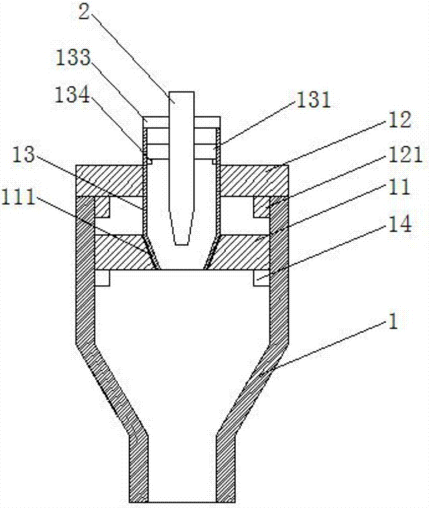
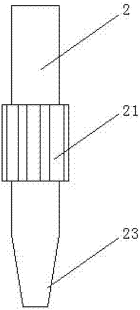
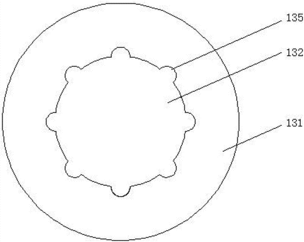
[0024] See Figure 1-4 , The present invention provides a technical solution: a medical testing sample filling device, comprising a measuring cup 1 and a sampling needle 2, the inside of the measuring cup 1 is installed with a first soft plug 11, the first soft plug 11 A tapered hole 111 is opened in the center, and the lower end of the tapered hole 111 communicates with the bottom surface of the first soft plug 11. The upper end of the ...


PUM


Abstract

The invention discloses a medical detection sample filling device which comprises a measuring cup and a sampling needle. A first soft plug is mounted in the measuring cup, a conical hole is formed in the center of the first soft plug, the lower end of the conical hole is communicated with the bottom surface of the first soft plug, a cup cover is mounted at the upper end of the measuring cup, a convex ring is fixedly arranged on the lower surface of the cup cover, a circular hole is formed in the middle of the cup cover, an outflow pipe is mounted on the cup cover through the circular hole, a second soft plug is mounted on the middle upper portion of the inner side of the outflow pipe, a circular through hole is formed in the middle of the second soft plug, a pipe cover is mounted at the upper end of the outflow pipe, the sampling needle is mounted in the middle of the pipe cover, and the lower end of the sampling needle penetrates the circular through hole in the middle of the second soft plug and is mounted at the inner lower end of the outflow pipe. According to the filling device, collecting accuracy of whole blood samples is high, mixing effect is good, replacement is easily achieved, a measuring cup body cannot be damaged, and the device is good in sealing effect and easy to popularize.

Description

Technical field [0001] The invention relates to the field of medical equipment, and in particular to a medical testing sample filling device. Background technique [0002] The five-category white blood cell automatic blood cell analyzer used in the clinical blood routine project requires micro blood sampling, which requires about 60 microliters of whole blood sample for measurement, and the whole blood sample needs to be injected into different measuring cups, for each measurement The whole blood sample filled in the cup is only a dozen microliters. When the sampling needle extends into the measuring cup to fill the whole blood sample, the whole blood sample inside the sampling needle is pushed by the syringe pump to form a sample at the lower end of the sampling needle. Small droplets, the diluent flows out from the cleaning part of the outer wall of the sampling needle, flows down the outer wall of the sampling needle, and fills the whole blood sample hanging on the lower end o...

Claims


Application Information

Patent Timeline
IPC IPC(8): G01N35/10
CPCG01N35/1079G01N2035/1032
Inventor 王岩岩赵崇智赵崇明熊寿园王康
Owner 马鞍山岩东精密仪器科技有限公司
Why Eureka
Try Eureka