
Method for removing interference on radar imaging caused by object micro-motion

A radar imaging and target technology, applied in the direction of reflection/re-radiation of radio waves, use of re-radiation, measurement devices, etc., can solve the problems of lack of convincing, no experimental data, etc., and achieve the effect of eliminating interference and clear imaging results

Inactive Publication Date: 2017-09-05
NAT SPACE SCI CENT CAS +1
View PDF5 Cites 20 Cited by
  • Summary
  • Abstract
  • Description
  • Claims
  • Application Information

AI Technical Summary

Problems solved by technology

The above methods are only used in simulation data, without experimental data, lack of convincing

Method used


Image

  • Method for removing interference on radar imaging caused by object micro-motion
  • Method for removing interference on radar imaging caused by object micro-motion
  • Method for removing interference on radar imaging caused by object micro-motion

Examples


Embodiment Construction

[0058] The present invention will be described in detail below in conjunction with the accompanying drawings and specific embodiments.

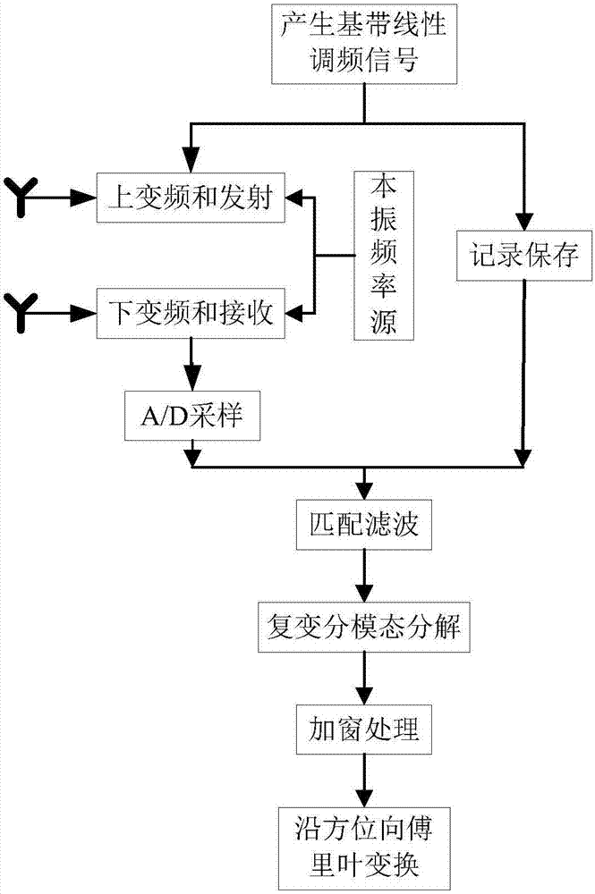
[0059] like figure 1 As shown, a method for eliminating target micro-movement interference to radar imaging, the method includes:

[0060] Step 1) The radar transmits M identical N-dimensional discretized chirp signals; after the transmitted signal and the received echo signal are matched and filtered, a two-dimensional distance-slow time domain echo with M rows and N columns is obtained. Wave data, express this echo data matrix as Specifically include:

[0061] Step 101) generating M identical baseband chirp signals, discretizing each signal;

[0062] Radar can only achieve high range resolution by transmitting a chirp signal once, and it still cannot identify targets in different azimuth positions, so imaging cannot be achieved. To obtain an image of the target, a cluster of these chirps needs to be transmitted. The transmitted M chir...


PUM


Abstract

The invention discloses a method for removing interference on radar imaging caused by object micro-motion. The method of the invention comprises steps of emitting M identical N-dimension discretized linear frequency modulation signals by a radar, obtaining an M-row and N-column two-dimensional distance-slow time domain echo data after an emitted signal and a received echo signal go through matched filtering, 2) performing compound variational mode decomposition on the distance-slow-time domain echo data of each column to obtain q modular functions, calculating energy of each modular function which is decomposed out, solving a ratio of energy of each modular function to energy of all modular functions, performing summation synthesis on the modular functions, the ratios of which are higher than a threshold to obtain new M-row N-column two-dimensional distance-slow-time-domain echo data and 3) performing windowing processing on the echo data of the M-row N-column two-dimensional distance-slow-time-domain which is obtained from the step 2 and then performing Fourier transformation along an azimuth to obtain an inverse synthesis aperture radar imaging.

Description

technical field [0001] The invention relates to the field of radar imaging and micro-Doppler effect, in particular to a method for eliminating the interference of target micro-movement on radar imaging. Background technique [0002] In (inverse) synthetic aperture radar imaging, the motion of the target can be decomposed into two parts: translation and rotation. The translation of the target produces the same Doppler shift for all scatter points, so the translational component does not contribute to the radar image. The rotational component of the target causes the echoes to have different envelope delays and phases. Because the translation of the target will cause the distance migration of the echo, resulting in the inability to obtain a good focused image, therefore, it is necessary to compensate the translation component first. Motion compensation consists of two parts: envelope alignment and phase correction. After motion compensation, an ideal turntable model can be ...

Claims


Application Information

Patent Timeline
IPC IPC(8): G01S13/90G01S7/02
CPCG01S7/023G01S13/904G01S13/9064
Inventor 康文武张云华董晓
Owner NAT SPACE SCI CENT CAS
Learn More