Keyboard clamping mechanism based on double effects of pressure and suction

A dual-action, clamping mechanism technology, applied in the direction of workpiece clamping devices, manufacturing tools, etc., can solve the problems of products being crushed, unable to ensure the pressure, and occupying a large space, so as to achieve convenient operation and easy maintenance , the effect of compact structure

Active Publication Date: 2017-09-08
珠海市运泰利自动化设备有限公司
View PDF7 Cites 4 Cited by
  • Summary
  • Abstract
  • Description
  • Claims
  • Application Information

AI Technical Summary

Problems solved by technology

Since the vacuum components are generally long in length, and each vacuum component needs to be connected to a separate air pipe, this kind of structure is more complicated, occupies a large space, and the air pipes are more unsightly and not in line with the simplicity of installation and maintenance. It also limits the number of vacuum nozzles installed. Since the number of vacuum nozzles cannot be arranged too much, the product adsorption force may not be enough to overcome the elastic force generated by the recovery of the keyboard after plastic deformation, resulting in the risk that the product cannot be adsorbed flat larger
Vacuum adsorption Since the maximum vacuum negative pressure will not exceed 1 atmospheric pressure, the suction force of each vacuum nozzle is certain and cannot be increased infinitely. When the suction force is less than the elastic force required by the keyboard to overcome the deformation, the vacuum will be destroyed and the keyboard cannot be sucked tightly
Due to the unevenness of the product, after placing the product, the operator needs to lightly press the product with his hand to make it touch the vacuum nozzle flatly so that it can be absorbed. bad risk
[0006] Therefore, whether it is the fixing method of the pressure plate module or the fixing method of vacuum adsorption, it cannot guarantee that all the keyboards to be tested can be fixed flat

Method used


Image

  • Keyboard clamping mechanism based on double effects of pressure and suction
  • Keyboard clamping mechanism based on double effects of pressure and suction
  • Keyboard clamping mechanism based on double effects of pressure and suction

Examples


Embodiment Construction

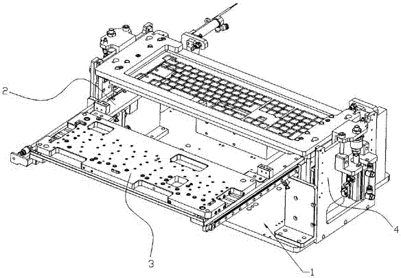
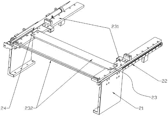
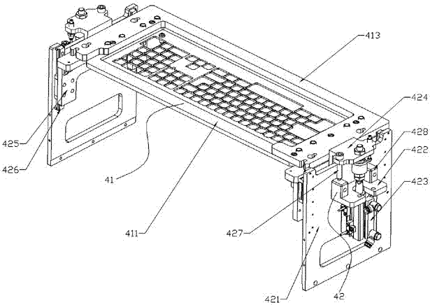
[0022] Such as Figure 1 to Figure 6 As shown, in this embodiment, the present invention includes a base plate 1, an in-out mechanism 2, a vacuum adsorption carrying mechanism 3 and a platen pressing mechanism 4, the in-out mechanism 2 is fixedly installed on the base plate 1, and the vacuum adsorption carrying mechanism 3 Slidingly fit with the entry and exit mechanism 2, the pressure plate mechanism 4 is arranged above the entry and exit mechanism 2, the entry and exit mechanism 2, the vacuum adsorption carrying mechanism 3 and the pressure plate mechanism 4 are all connected with the external MCU control module electrical connection.

[0023] This design combines two methods of clamping plate fixing and vacuum adsorption fixing to clamp the product, which provides a reliable fixing method for high-precision testing of the product; moreover, the invention has a compact, light, simple structure, convenient operation, and easy maintenance.

[0024] In this embodiment, the ent...


PUM


Abstract

The invention discloses a keyboard clamping mechanism based on double effects of pressure and suction. The keyboard clamping mechanism based on the double effects of pressure and suction combines a pressing plate module fixing mode and a vacuum adsorption fixing mode and enables a to-be-tested keyboard to be flatly fixed. The keyboard clamping mechanism based on the double effects of pressure and suction comprises a bottom plate, an entering-exiting mechanism, a vacuum adsorption carrying mechanism and a pressing plate mechanism, wherein the entering-exiting mechanism is fixedly installed on the bottom plate, the vacuum adsorption carrying mechanism is in sliding fit with the entering-exiting mechanism, the pressing plate mechanism is arranged above the entering-exiting mechanism, and the entering-exiting mechanism, the vacuum adsorption carrying mechanism and the pressing plate mechanism are electrically connected with an external MCU control module. The keyboard clamping mechanism based on the double effects of pressure and suction is applied to the technical field of keyboard quality testing.

Description

technical field [0001] The invention relates to a keyboard clamping mechanism, in particular to a keyboard clamping mechanism based on the dual effects of pressure and suction. Background technique [0002] As a device for inputting instructions and data during computer operation, keyboards are one of the indicators for testing the quality of keyboards. In order to ensure the quality of each keyboard, various keyboard feel testing equipment has emerged as the times require. Since the keyboard to be tested in the keyboard feel test is generally a semi-finished product, that is, PCBA with buttons, the rigidity is not enough to ensure that it remains flat during assembly or moving, and it is often bent and deformed when it reaches the feel test station. However, if the keyboard is placed unevenly, it will affect the accuracy of the test results, so how to ensure that the keyboard is flat during the test is the focus of the entire test system. [0003] At this stage, most of th...

Claims


Application Information

Patent Timeline
Patent Type & Authority Applications(China)
IPC IPC(8): B25B11/00
CPCB25B11/00B25B11/005
Inventor 莫伟健黄万演李东昆阮惠鹏
Owner 珠海市运泰利自动化设备有限公司
Why Eureka
Try Eureka