Automatic equipment part clamping mechanism
A technology of automation equipment and clamping mechanism, which is applied in the direction of chucks, manipulators, program-controlled manipulators, etc., can solve the problems of indentation on the surface of parts, inconvenient clamping, and difficulty in meeting quality standards, etc., to achieve powerful clamping functions and protection Integrity, effect of avoiding indentation
- Summary
- Abstract
- Description
- Claims
- Application Information
AI Technical Summary
Problems solved by technology
Method used
Image

Examples
specific Embodiment approach
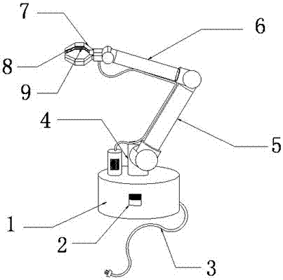
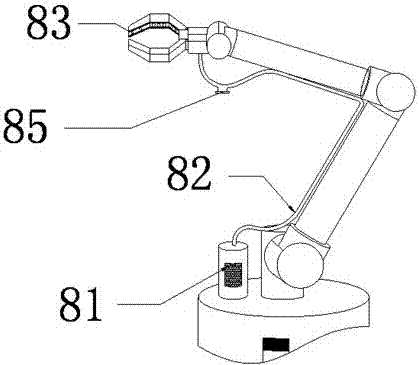
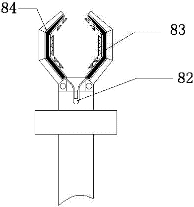
[0023] Specific embodiments: when the present invention clamps some parts with irregular surfaces, connect the power plug 3 to the power supply, turn on the control switch 2, and the inflator 81 starts to run, and the inflator 81 converts electrical energy into mechanical energy through the rubber hose 82 Inflate the strip-shaped airbag 83 installed in the airbag groove 84, and the strip-shaped airbag 83 will expand after inflation, thereby protruding from the end face of the mechanical claw 7, and avoiding excessive force when clamping parts with irregular surfaces. Indentation appears on the surface. After the clamping is completed, the air outlet 85 installed on the rubber hose 82 is opened to deflate the strip airbag 83, so that the strip airbag 83 shrinks into the airbag groove 84.
[0024] When the present invention clamps some parts with smooth and regular surfaces, rubber sucker 91 can be used to adsorb the parts with smooth and regular surfaces. 93 and rubber pad 2 94...
PUM
 Abstract
Description
Claims
Application Information