
Rear-end preventing drive assistance device based on 3D optical grating imaging principle

A grating imaging and driving assistance technology, which is applied in the direction of signal devices, optics, optical components, etc., can solve the problems of short detection distance, achieve low manufacturing cost, convenient maintenance, and reduce the effect of misjudgment rate

Active Publication Date: 2017-09-08
天岸马科技(黑龙江)有限公司
View PDF3 Cites 3 Cited by
  • Summary
  • Abstract
  • Description
  • Claims
  • Application Information

AI Technical Summary

Problems solved by technology

[0006] The present invention is to solve the problem of the short detection distance of the existing ranging detection technology, and now provides an anti-rear collision driving auxiliary device based on the principle of 3D raster imaging

Method used


Image

  • Rear-end preventing drive assistance device based on 3D optical grating imaging principle
  • Rear-end preventing drive assistance device based on 3D optical grating imaging principle
  • Rear-end preventing drive assistance device based on 3D optical grating imaging principle

Examples


specific Embodiment approach 1

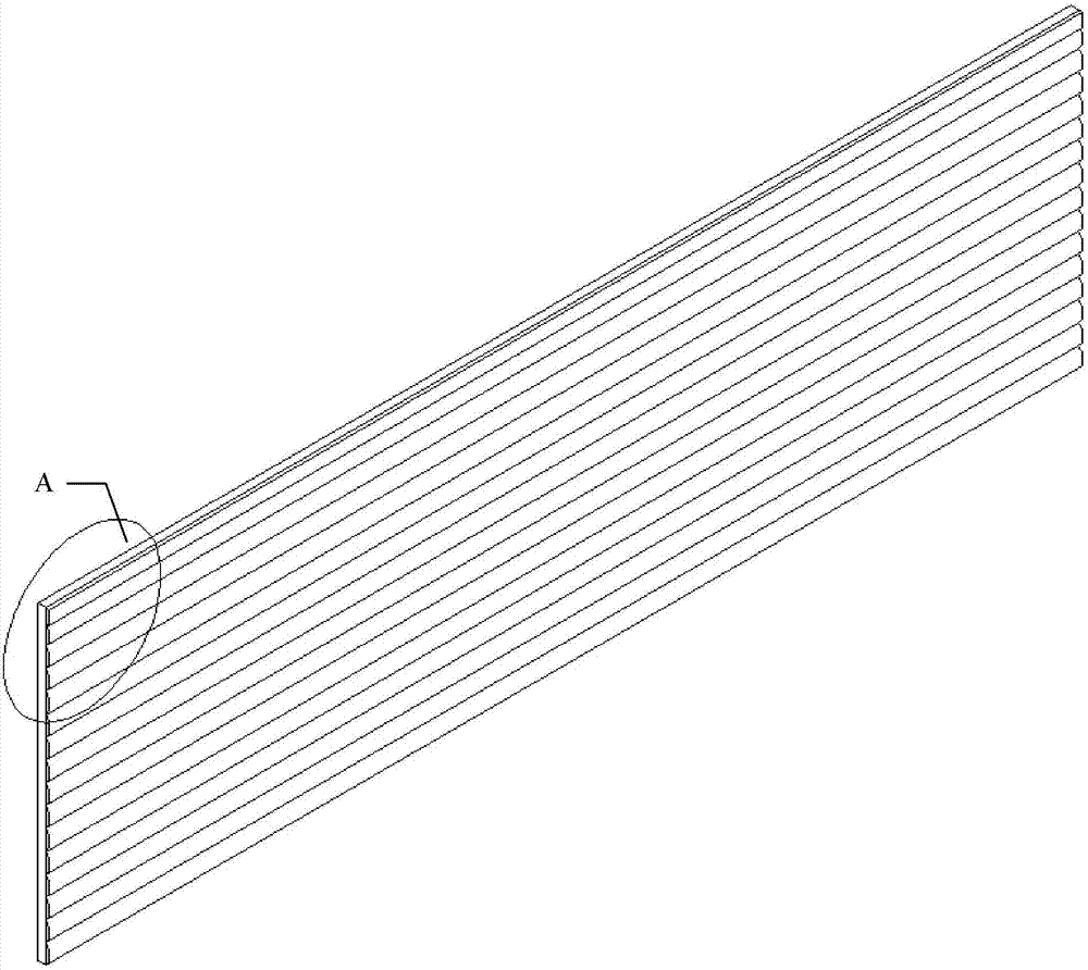
[0026] Specific implementation mode one: refer to Figure 1 to Figure 4 Describe this embodiment in detail. The anti-rear collision driving assistance device based on the 3D grating imaging principle described in this embodiment includes: a stripe picture 1 and a cylindrical lens grating, and the cylindrical lens grating is composed of a plurality of cylindrical lens elements 2;

[0027] The fringe picture 1 is set on the common focal plane of all the cylindrical lens elements 2 in the cylindrical lens grating;

[0028] Stripe painting 1 is composed of two kinds of wide and narrow solid color stripes arranged alternately. The two stripes have different colors.

[0029] The sum of the widths of the two stripes is equal to the grating pitch of the cylindrical lens grating,

[0030] The cross-section of the cylindrical lens element 2 is arcuate, and the arc of the cylindrical lens element 2 is 89°-90°,

[0031] The axes of a plurality of cylindrical lens elements 2 are all para...

specific Embodiment approach 2

[0048] Embodiment 2: This embodiment further explains the anti-rear-collision driving assistance device based on the principle of 3D grating imaging described in Embodiment 1. In this embodiment, it also includes LED lights 3,

[0049] The LED lamp 3 is fixed on the outside of the outermost cylindrical lens unit 2,

[0050] The light emitted by the LED lamp 3 is white light.

[0051] In this embodiment, an LED lamp 3 is added to illuminate the stripe pattern 1 and the plurality of cylindrical lens elements 2 . In actual use, the driver turns on the LED light 3 according to the ambient light conditions so that the driver of the rear car can observe.

specific Embodiment approach 3

[0052] Specific embodiment three: this embodiment is a further description of the anti-rear-collision driving assistance device based on the principle of 3D raster imaging described in specific embodiment one or two. In this embodiment, it also includes a suction cup,

[0053] The suction cup is fixed on the back of the stripe painting 1, and is used for fixing the anti-rear-end collision driving assistance device on the rear of the car.

[0054] The anti-rear collision driving assistance devices are divided into two types, A and B, among which type A is suitable for small passenger cars, and type B is suitable for large passenger cars. The classification methods and heights from the ground are shown in the table:

[0055] Table 1 Installation location

[0056] Types of rear-end collision prevention aids Install the model Height from the ground (m) First A.C 0.5 Second B.D 1.9

[0057] The height from the ground is the height of the horizonta...


PUM


Abstract

The invention discloses a rear-end preventing drive assistance device based on a 3D optical grating imaging principle, relates to the field of vehicle fitting facilities and aims to solve the problem of short detection distance of an existing distance measurement detection technique. According to the rear-end preventing drive assistance device based on the 3D optical grating imaging principle, a cylindrical-lens optical grating is composed of multiple cylindrical-lens elements. A stripe painting is arranged on a common focal plane for all the cylindrical-lens elements in the cylindrical-lens optical grating and is formed by alternatively arranging wide and narrow pure-colored stripes, the two stripe colors are different, the sum of the widths of the two stripes is equal to the distance of the cylindrical-lens optical grating, the axial directions of the multiple cylindrical-lens elements are parallel to the stripes on the stripe painting, and all the narrow stripes on the stripe painting correspond to the multiple cylindrical-lens elements respectively in a one-to-one mode and are aligned to the middles of the corresponding cylindrical-lens elements. The rear-end preventing drive assistance device is applied to the field of vehicle distance detection.

Description

technical field [0001] The invention belongs to the field of vehicle accessory facilities, in particular to an anti-rear-end collision driving auxiliary device. Background technique [0002] As a modern transportation infrastructure, high-grade highways (second-class highways and above-level highways) have become the lifeline projects supporting the growth of the national economy due to their large traffic volume, fast driving speed, complete facilities, and comfortable environment. By the end of 2015, the total mileage of my country's secondary and above highways had exceeded 574,900 kilometers, ranking first in the world. However, according to relevant statistics, the accident rate of high-grade highways in my country is much higher than that of low-grade highways (roads below the second grade), and the accident rate of expressways alone is 4 times that of ordinary roads. occurred, resulting in immeasurable loss of life and property. Through the summary and analysis of tr...

Claims


Application Information

Patent Timeline
Patent Type & Authority Applications(China)
IPC IPC(8): B60Q9/00G02B27/22
CPCB60Q9/008G02B30/27
Inventor 石惠铎李效松崔洪涛那玮伦王田宇
Owner 天岸马科技(黑龙江)有限公司
Learn More