
Drill pipe loading arm for pumping reverse circulation drilling machine

A pump suction reverse circulation, loading and unloading arm technology, applied in the direction of drill pipes, drill pipes, drilling equipment, etc., can solve the problems of heavy physical exertion of the operator, prone to accidents, unfavorable safety production, etc., to achieve convenient, fast and free installation The effect of large scale and simple structure

Pending Publication Date: 2017-09-08
ZHEJIANG ZHONGRUI ENG MACHINERY
View PDF8 Cites 1 Cited by
  • Summary
  • Abstract
  • Description
  • Claims
  • Application Information

AI Technical Summary

Problems solved by technology

[0002] At present, domestic pump suction reverse circulation drilling rigs use manual loading and unloading of drill pipes during construction, which is labor-intensive, and due to the weight of the drill pipe itself, working for a long time will consume a lot of physical strength for the operator and is prone to accidents. affect work efficiency
At the same time, there are also potential safety hazards, which are not conducive to safe production.

Method used


Image

  • Drill pipe loading arm for pumping reverse circulation drilling machine
  • Drill pipe loading arm for pumping reverse circulation drilling machine

Examples


Embodiment

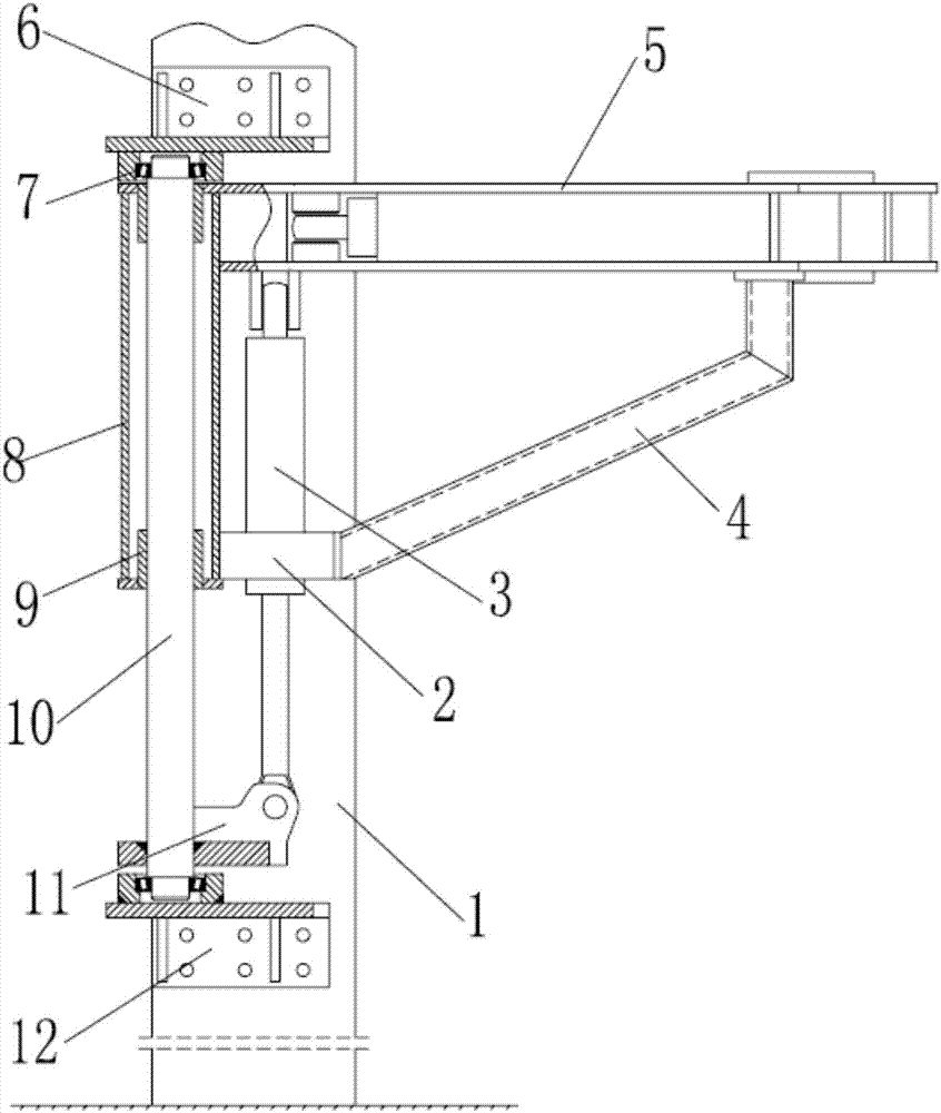
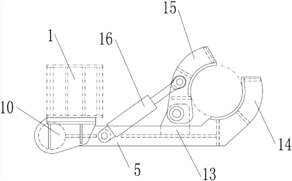
[0020] The movable clamp arm 15 and the fixed clamp arm 14 are pushed by the clamp arm cylinder 16 to clamp the drill pipe, the fixed clamp arm support 5 can rotate around the rotating shaft 10, and the movable clamp arm 15 and the fixed clamp arm 14 rotate with the fixed clamp arm support 5 To complete the centering or removal of the drill pipe; the lifting cylinder 3 drives the fixed clamp arm bracket 5 to move up and down, the fixed clamp arm bracket 5 slides up and down along the bearing 7 through the guide sleeve 8, and the movable clamp arm 15 and the fixed clamp arm 14 clamp the drill rod As the clamp arm support 5 moves up and down, the up and down movement of the drill rod is realized for the connection and disassembly of the drill rod. The upper and lower openings of the guide sleeve 8 are equipped with wear-resistant sleeves 9, and the wear-resistant sleeves 9 are sleeved on the rotating shaft 10. When the wear-resistant sleeve 9 is severely worn, only the wear-resi...


PUM


Abstract

The invention relates to a drill pipe loading arm for a pumping reverse circulation drilling machine. The drill pipe loading arm comprises a stand column, a lifting oil cylinder and a rotating shaft, a rotating shaft is vertically arranged on the front end face of the stand column, the upper end and the lower end of the rotating shaft are connected with the stand column through bearings, a guide sleeve is installed on the rotating shaft in a sliding mode, a fixed clamping arm support is transversely arranged on one side of the upper portion of the guide sleeve, the lifting oil cylinder is vertically installed at the lower end of the fixed clamping arm support, the middle of the lifting oil cylinder is connected with the lower portion of the guide sleeve through a guide bushing, a piston rod stretching out of the lower end of the lifting oil cylinder is connected with a support base arranged at the bottom of the rotating shaft in a sleeving mode, a fixed clamping arm is installed at one end of the fixed clamping arm support, a movable clamping arm is rotationally installed on the position, close to the fixed clamping arm, of the fixed clamping arm support, a clamping arm oil cylinder is rotationally installed in the middle of the fixed clamping arm support, and the piston rod of the clamping arm oil cylinder is rotationally connected with the middle of the movable clamping arm. Accordingly, a drill pipe is clamped and then moves to be aligned, and disassembling and assembling of the drill pipe are conducted through up-and-down motion.

Description

technical field [0001] The invention relates to the technical field of pump suction reverse circulation drilling rigs, in particular to a drilling rod loading and unloading arm for pump suction reverse circulation drilling rigs. Background technique [0002] At present, domestic pump suction reverse circulation drilling rigs use manual loading and unloading of drill pipes during construction, which is labor-intensive, and due to the weight of the drill pipe itself, working for a long time will consume a lot of physical strength for the operator and is prone to accidents. And affect work efficiency. There are also potential safety hazards, which are not conducive to safe production. In order to reduce labor intensity, improve production efficiency, and ensure safe production, a device is urgently needed to solve this type of problem. Contents of the invention [0003] The technical problem to be solved by the present invention is to provide a drill rod loading and unloadi...

Claims


Application Information

Patent Timeline
Patent Type & Authority Applications(China)
IPC IPC(8): E21B19/18
CPCE21B19/18
Inventor 张良夫吴岳张健于凯
Owner ZHEJIANG ZHONGRUI ENG MACHINERY
Learn More