Oil injector armature quick response structure

A fast-response, fuel injector technology, applied in the direction of machines/engines, fuel injection devices, engine components, etc., can solve the problems of hindering the axial movement of the armature, and the reaction speed of the armature cannot be further improved, so as to reduce the flow resistance and reduce the ineffectiveness Injection timing, effect of improving stability

Pending Publication Date: 2017-09-08
东莞市盈森汽车电喷科技有限公司
View PDF12 Cites 0 Cited by
  • Summary
  • Abstract
  • Description
  • Claims
  • Application Information

AI Technical Summary

Problems solved by technology

In the structure of the traditional valve body mechanism, the iron core tube at the lower part of the armature is connected to the ball valve, and the opening of the upper flow channel of the iron core tube adopts radial flow holes. The radial flow of the oil flow hinders the axial movement of the armature, which causes the armature An important reason why the reaction speed cannot be further improved

Method used


Image

  • Oil injector armature quick response structure
  • Oil injector armature quick response structure

Examples


Embodiment Construction

[0013] The technical solutions of the present invention will be further described below in conjunction with the embodiments shown in the accompanying drawings.

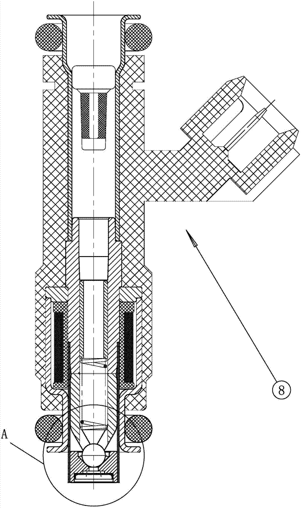
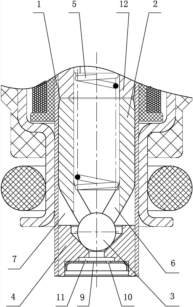
[0014] The rapid response structure of the armature of the fuel injector of the present invention, its technical solution includes a valve body structure arranged at the lower port of the magnetic isolation tube 1 at the nozzle (A) of the fuel injector 8, and the valve body structure includes a top-down coaxial Armature 2, ball valve 3, valve seat 4 and deflector 9, such as figure 1 , figure 2 shown.

[0015] The armature 2 includes an upper circular tube and a lower conical tube (the cone angle is downward). A flow-through cone cavity 7 is formed between the conical tube of the armature 2 and the magnetic isolation tube 1. The internal pressure of the circular tube of the armature 2 is equipped with a return spring. 5. The ball valve 3 is fixedly connected to the bottom of the lower conical tube of the armature 2....


PUM

PropertyMeasurementUnit
Cone angleaaaaaaaaaa

Abstract

The invention discloses an oil injector armature quick response structure. The oil injector armature quick response structure comprises a valve body structure arranged at a spray nozzle. The valve body structure comprises an armature, a ball valve and a valve seat which are coaxially arranged in a plunger tube. The armature comprises an upper round tube and a lower conical tube with the cone angle downwards. A conical flow cavity is formed between the conical tube and the plunger tube. Axial flow holes are uniformly formed in the circumference of the conical tube and communicate with the conical flow cavity. The ball valve is arranged at the bottom of the conical tube. A return spring is arranged in the round tube in a press-fitting mode. Under the action of elastic force of the return spring, the armature presses the ball valve tightly downwards and seals the ball valve in a conical oil supply hole, communicating with the conical flow cavity, of the valve seat. According to the structure, the flow holes are axially formed in the conical tube of the lower portion of the armature to replace a radial flow passage of a traditional structure; the flow resistance of fluid is lowered; the axial motion speed of the armature is increased; the invalid oil injection time of an oil injector is reduced; a dynamic flow nonlinear area is decreased; and the stability of the oil injector is improved.

Description

technical field [0001] The invention relates to an internal structure of an electronically controlled fuel injector, in particular to a fast response structure of an armature of the fuel injector. Background technique [0002] The fuel injector is used in precise metering and atomization of pulsating liquid, such as engine fuel metering and combustion control. The fuel injector receives the fuel injection pulse signal sent by the ECU (Electronic Control Unit) to precisely control the fuel injection quantity. [0003] The structure of the injector is mainly composed of electromagnetic mechanism, valve body mechanism, atomization mechanism, metering mechanism and flow channel mechanism. [0004] The rapid response of fuel injection of the injector is an important technical index, which is reflected in the action speed of the armature pull-in and return. In the structure of the traditional valve body mechanism, the iron core tube at the lower part of the armature is connected ...

Claims


Application Information

Patent Timeline
IPC IPC(8): F02M51/06F02M61/04F02M61/18
CPCF02M51/0664F02M61/04F02M61/188
Inventor 林林涛
Owner 东莞市盈森汽车电喷科技有限公司
Why Eureka
Try Eureka