Fast oil applying device for chain

A chain and fast technology, applied in the field of chains, can solve the problems of low automation, low practicability, low oiling efficiency, etc., achieve good oiling effect, realize oiling process, and high oiling efficiency

Inactive Publication Date: 2017-09-08
SUZHOU SHUNGE INTELLIGENT TECH
View PDF7 Cites 4 Cited by
  • Summary
  • Abstract
  • Description
  • Claims
  • Application Information

AI Technical Summary

Problems solved by technology

[0004] Chains are generally metal links or rings, mostly used for mechanical transmission, traction, and chains used to obstruct traffic passages (such as in streets, rivers or harbor entrances). Chains are divided into transmissions according to different uses and functions. There are four types of chains, conveyor chains, traction chains and special special chains. Among similar products, the chain products are divided according to the basic structure of the chain, that is, according to the shape of the components, the parts and parts meshing with the chain, and the size ratio between the parts. series, there are many types of chains, but their basic structures are only the following, and others are deformations of these types. We can see from the above chain structures that most chains are composed of chain plates, chain pins, Shaft sleeves and other components, other types of chains just make different changes to the chain plate according to different needs, some are equipped with scrapers on the chain plate, some are equipped with guide bearings on the chain plate, and some are installed on the chain plate Rollers, etc. are installed on the top, these are all modifications for different application occasions, and the chain will be oiled before the actual application, but the oiling process of many chains at present is relatively cumbersome, the oiling efficiency is low, and The degree of automation is low, so the practicability is not high

Method used


Image

  • Fast oil applying device for chain

Examples


Embodiment Construction

[0019] The following will clearly and completely describe the technical solutions in the embodiments of the present invention. Obviously, the described embodiments are only some of the embodiments of the present invention, rather than all the embodiments. Based on the embodiments of the present invention, all other embodiments obtained by persons of ordinary skill in the art without creative work fall within the protection scope of the present invention:

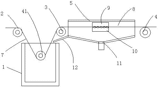
[0020] Such as figure 1 A quick oiling device for a chain is shown, comprising an oil cylinder 1, a first traction wheel 2, a second traction wheel 3, a third traction wheel 4, a transmission wheel 41 and an oil collection tank 5, the first traction wheel 2 And the second traction pulley 3 is placed on both sides of the upper cylinder mouth of the upper oil cylinder 1 and is oppositely arranged. The first traction pulley 2 and the second traction pulley 3 are driven to rotate by the driving motor, and the transmission wheel ...


PUM


Abstract

The invention discloses a fast oiling device for a chain, which comprises an oiling barrel, a first traction wheel, a second traction wheel, a third traction wheel, a transmission wheel and an oil collection tank, the first traction wheel and the second traction wheel are respectively It is placed on both sides of the upper mouth of the upper oil barrel and is set opposite to each other. The transmission wheel is placed in the upper oil barrel. The oil collection tank is placed on the upper part of the side of the oil upper barrel and is set horizontally. The oil collecting chamber passed through, the second traction wheel is placed at the entrance of the oil collecting chamber, the third traction wheel is placed at the outlet of the oil collecting chamber, and the upper oil collecting cotton and the lower oil collecting cotton are arranged in the oil collecting tank. There is a gap for the chain to pass between the cotton, the upper oil-collecting cotton and the lower oil-collecting cotton. The fast oiling device for the chain has a simple overall structure and is easy to install and operate, not only can effectively realize the fast oiling process of the chain, but also has high oiling efficiency without wasting lubricating oil, and has high practicability.

Description

[0001] Technical field: [0002] The invention relates to a fast oiling device for chains, and relates to the technical field of chains. [0003] Background technique: [0004] Chains are generally metal links or rings, mostly used for mechanical transmission, traction, and chains used to obstruct traffic passages (such as in streets, rivers or harbor entrances). Chains are divided into transmissions according to different uses and functions. There are four types of chains, conveyor chains, traction chains and special special chains. Among similar products, the chain products are divided according to the basic structure of the chain, that is, according to the shape of the components, the parts and parts meshing with the chain, and the size ratio between the parts. series, there are many types of chains, but their basic structures are only the following, and others are deformations of these types. We can see from the above chain structures that most chains are composed of chain ...

Claims


Application Information

Patent Timeline
Patent Type & Authority Applications(China)
IPC IPC(8): F16N7/28F16N31/02
CPCF16N7/28F16N31/02F16N2210/33
Inventor 戴双林何汉朝
Owner SUZHOU SHUNGE INTELLIGENT TECH
Why Eureka
Try Eureka