
Protection type precise setting-out position finder

A locator and precise technology, applied in the direction of instruments, measuring instruments, measuring devices, etc., can solve the problems of difficult maintenance, insufficient reliability of the fixing method, and increasing the cumbersome installation, so as to achieve a reliable structure, an uncomplicated structure, and reduced The effect of small assembly difficulty

Pending Publication Date: 2017-09-08
CHINA NAT DECORATION
View PDF5 Cites 4 Cited by
  • Summary
  • Abstract
  • Description
  • Claims
  • Application Information

AI Technical Summary

Problems solved by technology

[0019] In order to solve the above-mentioned problems, the present invention provides a projection-type precise setting-out locator, which effectively reduces the loss of connection and erection effects of the couplings in the prior art, increases the cumbersome installation, and makes maintenance difficult. The defect that the fixed connection method is often insufficient in reliability

Method used


Image

  • Protection type precise setting-out position finder
  • Protection type precise setting-out position finder
  • Protection type precise setting-out position finder

Examples


Embodiment 1

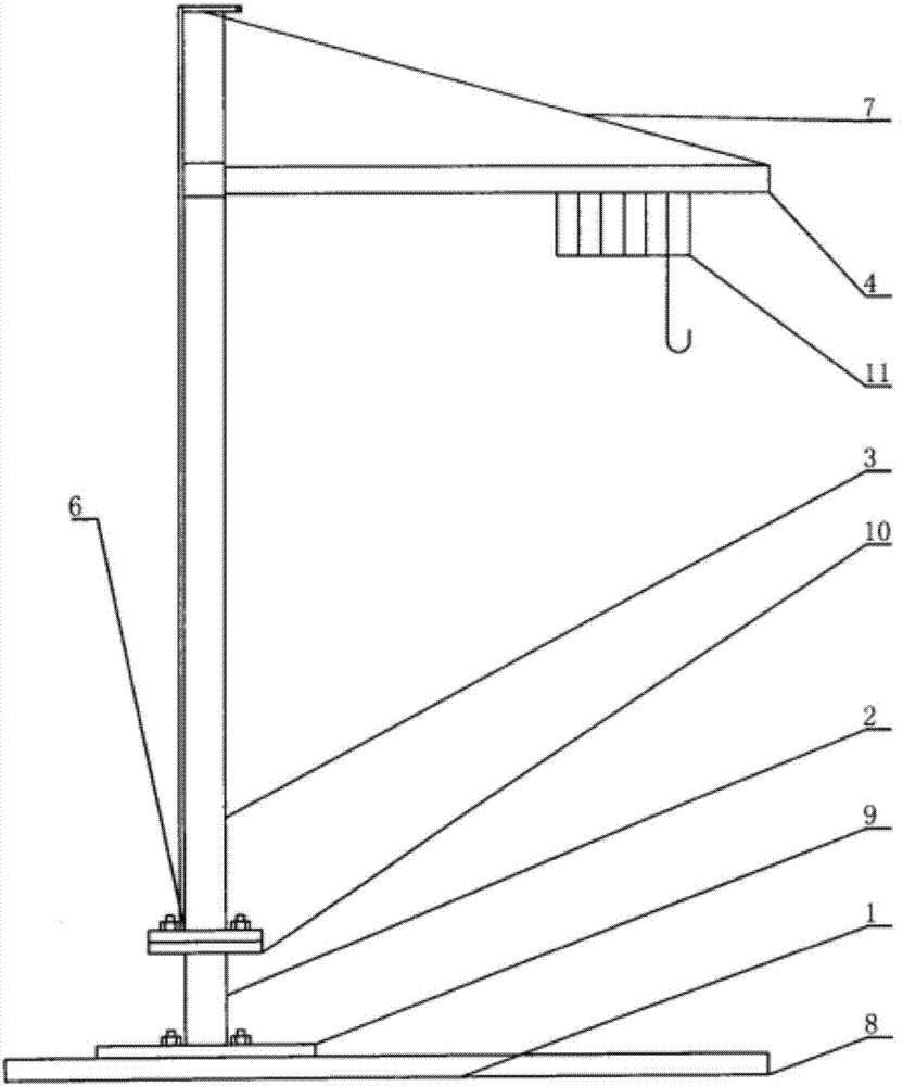
[0054] Such as Figure 1-Figure 5 As shown, the projection-type accurate wire-laying locator of the present embodiment includes: a cylindrical cone rod 3, a square base 1, a wire reel 7 for vertically telescopic wire-laying, a vertical wire 4, and a wire for connecting the vertical wire. The crossbeam 5, the spirit level positioner 6 and the four adjustment screws 2 for adjusting the verticality;

[0055] Wherein, the bottom end of the cylindrical cone rod 3 is inserted into the square base 1;

[0056] The four corners of the upper surface of the square base 1 are respectively provided with the four adjusting screws 2 for adjusting verticality;

[0057] The top of the cylindrical cone rod 3 is vertically connected with the beam 5 for connecting vertical lines;

[0058] The level locator 6 is set under the cylindrical cone rod 3;

[0059] Both ends of the vertical line 4 are respectively connected to the square base 1 and the beam 5 for connecting the vertical line;

[0060...

Embodiment 2

[0082] The projection-type accurate wire-laying positioning instrument of this embodiment includes: a cylindrical cone rod 3, a square base 1, a wire reel 7 for vertical telescopic wire-laying, a vertical wire 4, and a crossbeam 5 for connecting the vertical wire , a spirit level locator 6 and four adjustment screws 2 for adjusting verticality;

[0083] Wherein, the bottom end of the cylindrical cone rod 3 is inserted into the square base 1;

[0084] The four corners of the upper surface of the square base 1 are respectively provided with the four adjusting screws 2 for adjusting verticality;

[0085] The top of the cylindrical cone rod 3 is vertically connected with the beam 5 for connecting vertical lines;

[0086] The level locator 6 is set under the cylindrical cone rod 3;

[0087] Both ends of the vertical line 4 are respectively connected to the square base 1 and the beam 5 for connecting the vertical line;

[0088] The wire reel 7 for vertical telescopic pay-off is c...

Embodiment 3

[0114] The projection-type accurate wire-laying positioning instrument of this embodiment includes: a cylindrical cone rod 3, a square base 1, a wire reel 7 for vertical telescopic wire-laying, a vertical wire 4, and a crossbeam 5 for connecting the vertical wire , a spirit level locator 6 and four adjustment screws 2 for adjusting verticality;

[0115] Wherein, the bottom end of the cylindrical cone rod 3 is inserted into the square base 1;

[0116] The four corners of the upper surface of the square base 1 are respectively provided with the four adjusting screws 2 for adjusting verticality;

[0117] The top of the cylindrical cone rod 3 is vertically connected with the beam 5 for connecting vertical lines;

[0118] The level locator 6 is set under the cylindrical cone rod 3;

[0119] Both ends of the vertical line 4 are respectively connected to the square base 1 and the beam 5 for connecting the vertical line;

[0120] The wire reel 7 for vertical telescopic pay-off is c...


PUM


Abstract

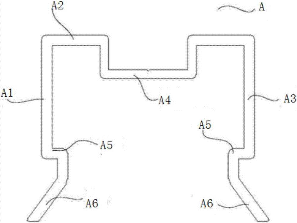
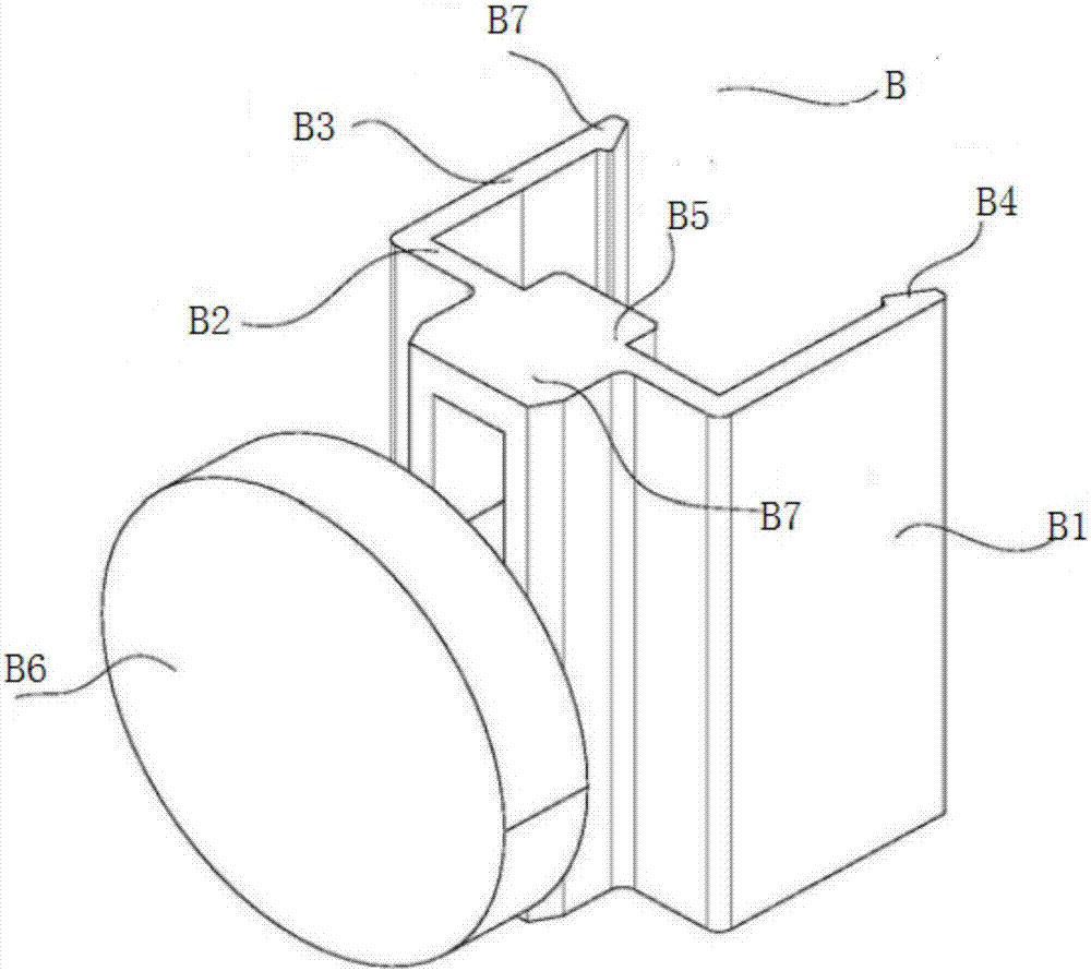
Provided is a protection type precise setting-out position finder. The position finder comprises a horizontal base of which the upper portion is provided with a bearing base, the bearing base is coordinated with a wall through a flange, and the upper portion of the wall is provided with an iron plate; the structure that the upper portion of the wall is provided with the iron plate is achieved by connecting the wall and the iron plate through a connecting piece, a first connecting piece and a third connecting piece are arranged oppositely, a notch-shaped connecting opening is formed in a second connecting piece, and the bottom wall of the connecting opening faces the direction far from the first connecting piece; the upper portion of the outer wall of the bottom of a square box is integrally connected to an iron material protrusion, the iron material protrusion is located outside the top of the iron plate, and the lower portion of the outer wall of the bottom of the square box is attached to a rubber sheet through viscose glue; a notch is formed in the top wall of the top of the iron plate, and the connecting opening is formed in the side wall in the connecting opening. Through the protection type precise setting-out position finder, the defects in the prior art that the effects of connecting and erecting are lost, the complication of mounting is improved, thus the maintenance becomes difficult, and the fixing and connecting method is always not stable enough caused by a connecting piece are reduced.

Description

technical field [0001] The invention relates to the technical field of setting-out locators, in particular to a projection-type precise setting-out locator. Background technique [0002] Ancient builders used ink strings to measure whether a house was built straight. Tie one end of the rope to an object, then paint ink on the rope, pick up the rope, and the heavy object tied at one end will go down vertically due to the gravity of the earth, and put it on the edge of the wall like this. If the wall is parallel to the rope, it means Walls are straight, otherwise they are crooked. The ink string mentioned here refers to the heavy vertical line. [0003] The vertical positioning technology of the existing construction projects has no specific positioning. The position is determined by human eyes and moved at any time manually, resulting in inaccurate position positioning and offset. The building bricks are not parallel and smooth, and the quality cannot be guaranteed. [000...

Claims


Application Information

Patent Timeline
Patent Type & Authority Applications(China)
IPC IPC(8): G01C15/00
CPCG01C15/00
Inventor 路春波
Owner CHINA NAT DECORATION
Learn More