
Airplane corrugated pipe sealing pressure testing clamp

A technology for sealing pressure and test fixtures, which is applied in the direction of liquid/vacuum measurement, measuring devices, instruments, etc., which can solve the problem of inability to fix the distance adjustment of the fulcrum, achieve easy installation and disassembly, operation and use, and has universality , The effect of convenient pressure test

Inactive Publication Date: 2017-09-08
SHENZHEN LANSITENG TECH
View PDF10 Cites 2 Cited by
  • Summary
  • Abstract
  • Description
  • Claims
  • Application Information

AI Technical Summary

Problems solved by technology

[0003] When the bellows are manufactured and processed by rolling waves, the pressure test should be carried out in advance to ensure that the pipeline does not leak. The Chinese invention patent "aircraft bellows sealing pressure test fixture", the patent application number is 201520777237.0, discloses a bellows sealing pressure The test fixture can meet the needs of fixing the pipe during the experiment, but there are still some shortcomings. Because the wall of the corrugated pipe is thin, it needs to be fixed on the outer wall near the end of the pipe. At the same time, the outer edge of the end face of the pipe should be sealed and fixed. To effectively control the distance between the two fixed fulcrums, the appropriate distance between the bellows is different for different sizes, and this patent cannot adjust the distance between the two fixed fulcrums

Method used


Image

  • Airplane corrugated pipe sealing pressure testing clamp
  • Airplane corrugated pipe sealing pressure testing clamp
  • Airplane corrugated pipe sealing pressure testing clamp

Examples


Embodiment Construction

[0025] In order to facilitate the understanding of the present invention, the present invention will be described in more detail below in conjunction with the accompanying drawings and specific embodiments. Preferred embodiments of the invention are shown in the accompanying drawings. However, the present invention can be implemented in many different forms and is not limited to the embodiments described in this specification. On the contrary, these embodiments are provided to make the understanding of the disclosure of the present invention more thorough and comprehensive.

[0026] It should be noted that when an element is referred to as being “fixed” to another element, it can be directly on the other element or there can also be an intervening element. When an element is referred to as being "connected to" another element, it can be directly connected to the other element or intervening elements may also be present. The terms "fixed", "integrated", "left", "right" and si...


PUM


Abstract

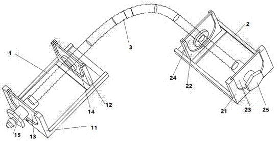
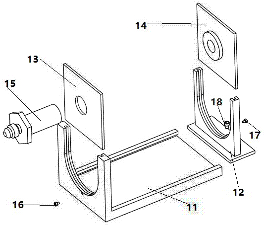
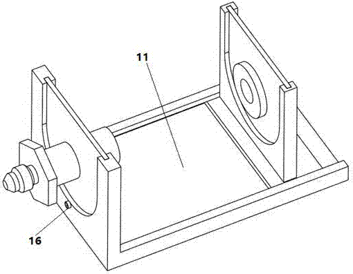
The invention discloses an airplane corrugated pipe sealing pressure testing clamp which comprises an adapter coupling mechanism and a sealing connector mechanism, wherein the adapter coupling mechanism is connected with one end of a corrugated pipe; the sealing connector mechanism is connected with the other end of the corrugated pipe; the adapter coupling mechanism comprises an adapter coupling base, an adapter coupling, an adapter mechanism sliding block, a first fixing block and a second fixing block; an adapter mechanism sliding groove and a first fixing groove are formed in the adapter coupling base; the adapter mechanism sliding block is matched with the adapter mechanism sliding groove; a second fixing groove is formed in the adapter mechanism sliding block; the first fixing block is mounted in the first fixing groove; the second fixing block is mounted in the second fixing groove; and the structural connections of the sealing connector mechanism and the adapter coupling mechanism are consistent. By adopting the airplane corrugated pipe sealing pressure testing clamp, the problem of positioning a corrugated pipe when the pressure of a rolling wave processed pipeline in airplane equipment is tested is effectively solved, double-fulcrum positioning is adopted in corrugated pipe positioning, the distance between two fixing fulcrums can be appropriately adjusted and controlled, and security, reliability and universality are achieved.

Description

technical field [0001] The invention relates to the technology of an auxiliary device for testing corrugated pipeline materials of aircraft equipment, in particular to a jig for testing the sealing pressure of the aircraft bellows. Background technique [0002] Bellows refers to a tubular elastic sensitive element connected by foldable corrugated sheets along the direction of folding and stretching. Bellows are widely used in instruments and meters, and their main purpose is as a measuring element of a pressure measuring instrument to convert pressure into displacement or force. The bellows has a thinner wall and higher sensitivity, and the measurement range is tens of Pa to tens of MPa. Its open end is fixed, and the sealed end is in a free state, and the auxiliary coil spring or reed is used to increase the elasticity. When working, under the action of internal pressure, it is elongated along the length of the pipe, so that the movable end produces a displacement that ha...

Claims


Application Information

Patent Timeline
Patent Type & Authority Applications(China)
IPC IPC(8): G01N3/04G01M3/02
CPCG01N3/04G01M3/02
Inventor 郑桂爱梁飞燕陈星灿
Owner SHENZHEN LANSITENG TECH
Learn More