
Pipe water-pressure detecting equipment

A technology for hydraulic testing and pipes, applied to measuring devices, using stable tension/pressure to test the strength of materials, instruments, etc., can solve the problems of large axial water sealing area, complex body structure, and high cost of use, and achieve water injection Less quantity, simple equipment structure and cost saving effect

Pending Publication Date: 2017-09-08
宁波友宁钢管有限公司
View PDF11 Cites 0 Cited by
  • Summary
  • Abstract
  • Description
  • Claims
  • Application Information

AI Technical Summary

Problems solved by technology

Although the testing machine achieves the purpose of hydraulic testing of steel pipes, due to the large diameter of the steel pipe and the large axial water sealing area, the high water pressure of the steel pipe test will generate a huge axial thrust, making the hydraulic testing machine The structure of the body is complex, heavy and costly. In addition, when performing hydraulic pressure testing on large-diameter steel pipes, it is necessary to fill the entire steel pipe with water. The amount of water injected is large and the cost of use is high.

Method used


Image

  • Pipe water-pressure detecting equipment

Examples


Embodiment Construction

[0018] The present invention will be further described in detail below in conjunction with the accompanying drawings and embodiments.

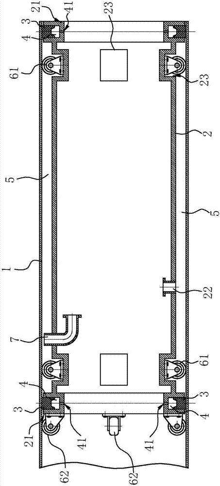
[0019] Such as figure 1 As shown, the pipe water pressure detection equipment of the embodiment of the present invention includes a cylinder 2 and a tensioning mechanism, wherein the cylinder 2 can be built into the pipe 1 to be tested, the inside of the cylinder 2 is hollow, and the two ends of the cylinder 2 are arranged There is an annular groove 21 with an opening facing outward, and a seal 3 is arranged in the annular groove 21; there are many ways to connect the cylinder body 2 and the annular groove 21, and the cylinder body 2 and the annular groove 21 can be integrally formed. The cylinder body 2 and the annular groove 21 can also be connected together by means of welding. In this embodiment, preferably, both ends of the cylinder body 2 are fixedly connected to an outer wall of the annular groove 21 by welding. structure.

[0020] Th...


PUM


Abstract

The invention relates to pipe water-pressure detecting equipment. The pipe water-pressure detecting equipment comprises a barrel body, and further comprises a tightening mechanism for enabling the barrel body and a to-be-detected pipe to form sealing connection through a sealing part, wherein the barrel body can be internally arranged in the to-be-detected pipe. The pipe water-pressure detecting equipment is characterized in that ring-shaped grooves with outward openings are formed in the two ends outside the barrel body, wherein sealing parts are arranged in the ring-shaped grooves,the external diameter of the barrel body is samller than the inner diameter of the to-be-detected pipe; under action of the tightening mechanism, the barrel body and the to-be-detected pipe are enclosed with the sealing part to form a water pressure cavity; and a water injecting hole for injecting water into the water pressure cavity is formed in the peripheral wall of the barrel body. According to the equipment, the barrel body is sealed with the to-be-detected tube through the sealing part by regulating hydraulic pressure, and needed water injection amount is less when water pressure detection is performed on the to-be-detected pipe, so that cost is saved; sealing tightness between the barrel body and the to-be-detected pipe is regulated to release gas in the water pressure cavity; and the equipment is simple in structure, is light in weight, is convenient to move and is not limited by length of the pipe, so that the pipe is detected section by section, and use is more convenient.

Description

technical field [0001] The invention relates to the technical field of hydraulic testing equipment, in particular to a pipe hydraulic testing equipment. Background technique [0002] At present, in order to ensure the quality of steel pipes, it is necessary to carry out hydrostatic test inspections on steel pipes for fluid transportation to grasp the degree of water pressure resistance and leakage resistance of the pipes, such as the Chinese utility model patent with the patent number CN03259259.0 (authorized announcement number CN2630835) "Large-diameter steel pipe hydraulic test device", the hydraulic test device includes a hydraulic device, and also includes a mandrel, two diversion channels are respectively provided at the shaft cores at both ends of the mandrel, and the entrance of the diversion channel is located on the mandrel The shaft end is connected with the hydraulic device, and the outlet of the other end is set on the outer circle of the mandrel. The two ends o...

Claims


Application Information

Patent Timeline
Patent Type & Authority Applications(China)
IPC IPC(8): G01N3/12
CPCG01N3/12G01N2203/0048G01N2203/0019
Inventor 朱才科
Owner 宁波友宁钢管有限公司
Learn More