
Microscopic imaging system for sample analysis

A technology of microscopic imaging and microscopic objective lens, which is applied in microscopes, optics, instruments, etc., can solve the problems of low image contrast and unfavorable image analysis and processing, and achieve the effect of improving contrast and photographing high-speed moving cells

Inactive Publication Date: 2017-09-08
SHENZHEN XIAOFU MEDICAL TECH CO LTD
View PDF0 Cites 4 Cited by
  • Summary
  • Abstract
  • Description
  • Claims
  • Application Information

AI Technical Summary

Problems solved by technology

The image resolution obtained by the existing microscope system is related to both the numerical aperture of the microscopic objective lens and the numerical aperture of the illumination. In use, the numerical aperture of the illumination is required to match the numerical aperture of the microscopic objective lens. Usually, the numerical aperture of the illumination is adjusted to the numerical aperture of the objective lens. 0.8 times the aperture, so that images with high resolution and appropriate contrast can be obtained at the same time, but this cooperation method is only suitable for observing and photographing cells that are still or moving slowly, while for planar flow imaging technology, cells move fast, If the numerical aperture of lighting and imaging is still configured in this way, the contrast of the captured image will be very low, which is not conducive to the subsequent analysis and processing of the image

Method used


Image

  • Microscopic imaging system for sample analysis
  • Microscopic imaging system for sample analysis
  • Microscopic imaging system for sample analysis

Examples


Embodiment Construction

[0021] The present invention will be further described in detail below in conjunction with the accompanying drawings, so that those skilled in the art can implement it with reference to the description.

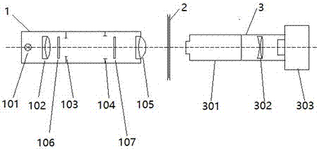
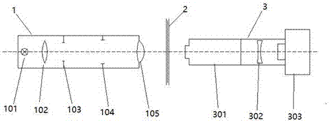
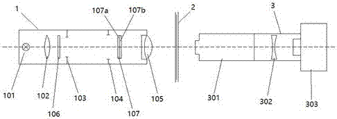
[0022] Refer to attached figure 1 As shown, the light source 101, the first lens group 102, the first diaphragm 103, the second diaphragm 104, the second lens group 105, the imaging cell 2, the microscope objective lens 301, and the third lens group 302 are sequentially arranged along the optical axis . The camera 303 constitutes the basic structure of the microscopic imaging system of the present invention. Wherein, the light source 101, the first lens group 102, the first diaphragm 103, the second diaphragm 104, and the second lens group 105 constitute the Kohler illumination unit 1; the microscope objective lens 301, the third lens group 302, and the camera 303 constitute the imaging Unit 3. The Kohler illumination unit 1 has a first numerical aperture; the microscopic o...


PUM


Abstract

The invention relates to a microscopic imaging system. The microscopic imaging system comprises a light source, a first lens group, a first diaphragm, a second diaphragm, a second lens group, an imaging pool, a microscope objective, a third lens group and a camera which are sequentially arranged along an optical axis, wherein the light source, the first lens group, the first diaphragm, the second diaphragm and the second lens group form a Kohler illumination unit; the microscope objective, the third lens group and the camera form an imaging unit; the Kohler illumination unit has a first numerical aperture, and the microscope objective has a second numerical aperture; and the ratio of the first numerical aperture and the second numerical aperture is not greater than 1 / 3. The microscopic imaging system appropriately reduces the illumination numerical aperture and improves the contrast of an image under the condition that the resolution of the image is acceptable, thereby being conducive to shooting high-speed moving cells, and being conducive to subsequent picture analysis and processing.

Description

technical field [0001] The invention relates to the field of microscopic imaging, in particular to a microscopic imaging system in a formed component analyzer using planar flow imaging technology. Background technique [0002] Planar flow imaging technology is a technology for analyzing tiny particles (such as cells) in liquid, and its components are liquid flow system, lighting system, imaging system, and control system. The liquid flow system is composed of the sample pool and the pipeline; the illumination system is composed of the light source and the Kohler illumination lens group; the imaging system is composed of the microscope objective lens, auxiliary objective lens and camera; the control system coordinates and manages the illumination system, liquid flow system, and imaging system work cooperatively. [0003] The liquid flow system of the formed component analysis instrument using planar flow imaging technology can make the liquid containing the cells to be analy...

Claims


Application Information

Patent Timeline
IPC IPC(8): G02B21/02G02B21/06
CPCG02B21/02G02B21/06
Inventor 杨洪武牛振兴刘博通刘磊王峰
Owner SHENZHEN XIAOFU MEDICAL TECH CO LTD
Learn More