Automatic monitoring system of vehicle with high-speed movement
A high-speed motion and automatic monitoring technology, which is applied in the traffic control system of road vehicles, traffic control system, traffic flow detection, etc., can solve the problems of demanding external environment and the inability of video technology to play a long-distance role
- Summary
- Abstract
- Description
- Claims
- Application Information
AI Technical Summary
Problems solved by technology
Method used
Image
Examples
Embodiment 1
[0028] The automatic monitoring system of the high-speed moving vehicle of the present invention uses the laser sensor and the radar speedometer to collect basic data synchronously, and transmits the data to the data processor, and then uses the data processor to describe the shape of the vehicle by constructing a mathematical model and designing an algorithm feature, determine its lane position, and perform vehicle speed feedback and data statistics.
Embodiment 2
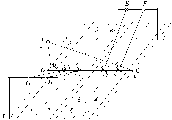
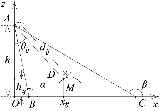
[0030] The automatic monitoring system of the high-speed moving vehicle of the present invention, as figure 1 As shown, the laser sensor is installed on the roadside of the road to be tested to scan the position of each point on the vehicle, and its installation height is h(h≥0) , the probe faces the road surface, the installation position of the probe is parallel to the cross-section of the road, and the scanning angle of the laser sensor is , install a radar speedometer on each lane, each radar speedometer is perpendicular to the intersection line between the laser sensor scanning surface and the road surface, and the installation height of each radar speedometer is the same, each radar speedometer to the laser sensor scanning surface and the road surface The distances of the intersecting lines are equal, the irradiation direction of the radar speedometer must face the laser sensor, and the installation angle of each radar speedometer is the same.
Embodiment 3
[0032] The hardware configuration of the automatic monitoring system of the high-speed moving vehicle of the present invention:
[0033] like figure 1 As shown, the gantry IGH and the gantry JFE are parallel to each other, perpendicular to the lane separation line, and are located on both sides of the expressway. The three points of J are installed at the nearest edge of the nearest lane and keep a certain distance, and the four points of E, F, G, and H are respectively installed with a radar measuring instrument. The radar speed measuring instrument is installed on the front of the front of the vehicle. Adjust the up, down, left, and right angles of the radar speedometer F, so that the most effective road speed measurement area is F S , adjust the other three radar speedometers in the same way, so that the most effective speed measurement areas of the three radar speedometers are G S、 h S、 E. S Four elliptical areas G S、 h S、 E. S、 f S The front, rear, left, and righ...
PUM
 Abstract
Description
Claims
Application Information
 - R&D
- Intellectual Property
- Life Sciences
- Materials
- Tech Scout
- Unparalleled Data Quality
- Higher Quality Content
- 60% Fewer Hallucinations
Browse by: Latest US Patents, China's latest patents, Technical Efficacy Thesaurus, Application Domain, Technology Topic, Popular Technical Reports.
© 2025 PatSnap. All rights reserved.Legal|Privacy policy|Modern Slavery Act Transparency Statement|Sitemap|About US| Contact US: help@patsnap.com


