Device for determining the rotational speed of a rotating machine part using redundant sensors and evaluation circuits

A technology of rotating machines and sensors, applied in the field of measurement, can solve the problems of losing reliability of results, achieve high availability and improve reliability

Inactive Publication Date: 2005-10-05
SIEMENS AG +1
View PDF1 Cites 9 Cited by
  • Summary
  • Abstract
  • Description
  • Claims
  • Application Information

AI Technical Summary

Problems solved by technology

[0016] The disadvantage of this known device is that the reliability of the result is lost when replacing the output signal of a faulty channel with a channel whose output signal is at the nominal value

Method used


Image

  • Device for determining the rotational speed of a rotating machine part using redundant sensors and evaluation circuits
  • Device for determining the rotational speed of a rotating machine part using redundant sensors and evaluation circuits
  • Device for determining the rotational speed of a rotating machine part using redundant sensors and evaluation circuits

Examples


Embodiment Construction

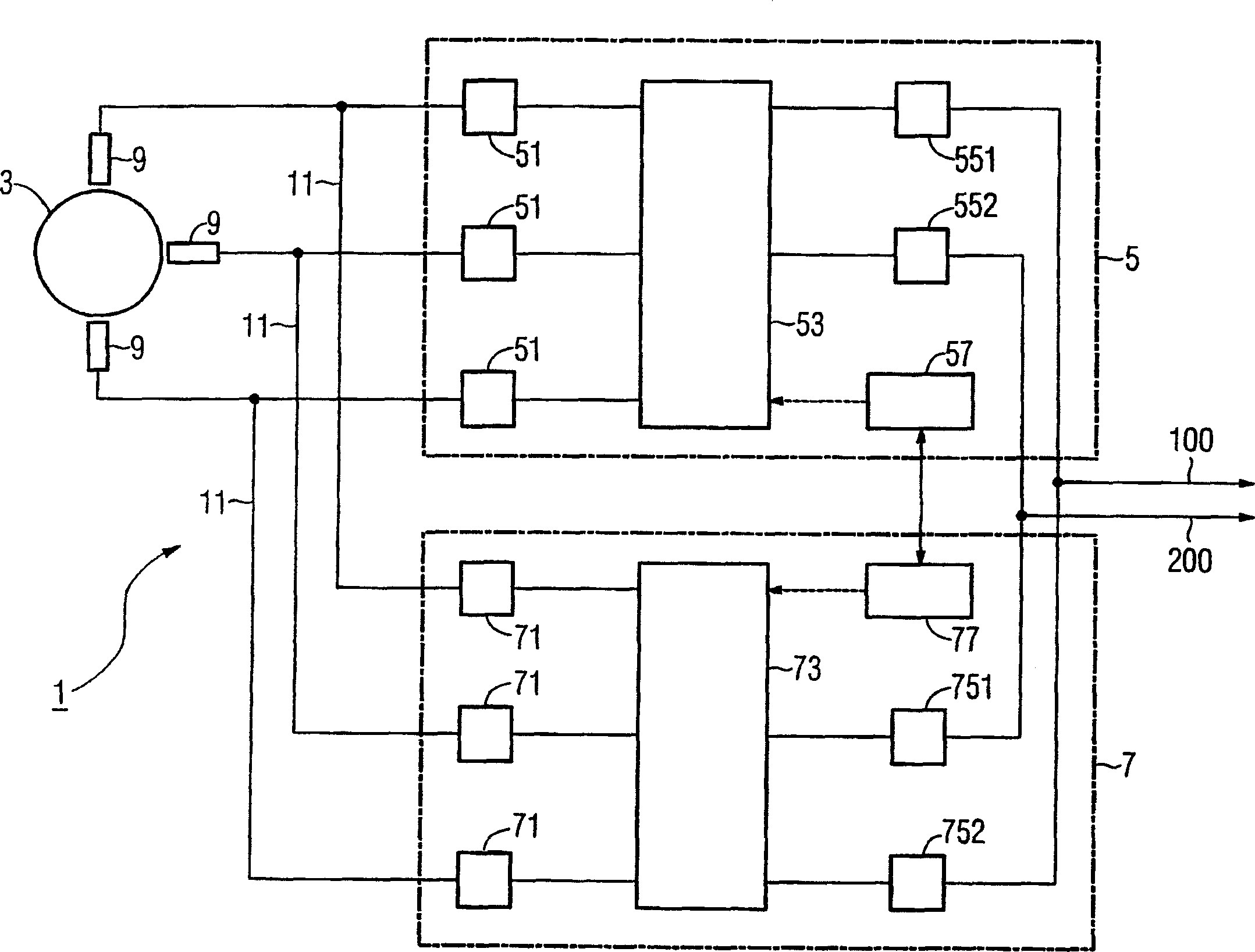
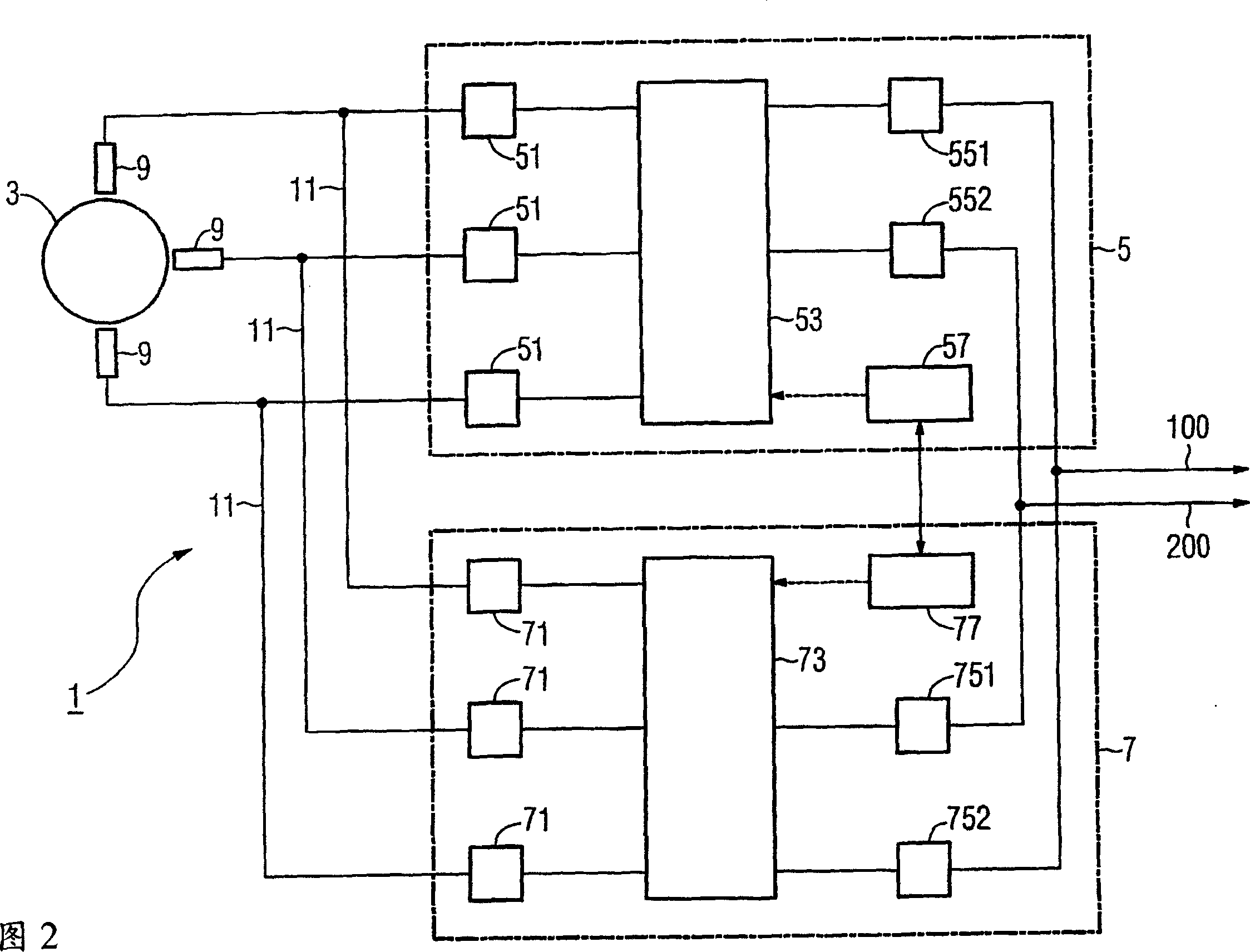
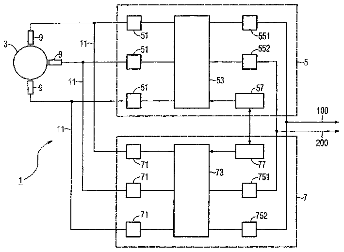
[0086] exist figure 1 A device 1 according to the invention for monitoring the number of revolutions of a rotating machine component 3 , in particular a turbine wheel, is shown in .

[0087] In order to detect the rotational speed signal of the rotating machine part 3 , three rotational speed sensors 9 are arranged on the wheel rim of the rotating machine part 3 , which sensors are arranged for example on the wheel rim and detect rotational marks or gear teeth during operation.

[0088] The output signal 11 of the rotational speed sensor 9 is connected in parallel with the signal input terminals 51 of the first component 5 and the second component 7, wherein the output signal 11 of one rotational speed sensor 9 is connected to the corresponding signal input terminals 51, 51, 71. The signal inputs 51 , 71 of the two components 5 , 7 are each connected to a computing unit 53 , 73 of the respective component 5 , 7 .

[0089] The speed of rotation of the rotary machine part 3 is...


PUM


Abstract

The invention relates to a device (1) which comprises two parallel partial devices (5, 7) that are provided with three signal inputs (51, 71) each for achieving a redundant two-out-of-three rotational speed detection. Every partial device (5, 7) comprises an arithmetic unit (53, 73) which is used to calculate the rotational speed of the rotating machine part (3). Every partial device (5, 7) furthermore comprises a signal output for outputting the rotational speed calculated by the respective arithmetic unit (51, 71). Matching signal inputs of the partial devices (5, 7) are connected in parallel to the output signal (11) of a rotational speed sensor (9). In an error case, the function of the inventive device can be completely taken over by one of the partial devices (5, 7) so that both a faulty output signal (11) of a rotational speed sensor (9) and a failure of one of the partial devices (5, 7) can be tolerated.

Description

technical field [0001] The invention relates to a device for monitoring the number of revolutions of a rotating machine part. [0002] The invention relates to the field of measurement technology, in particular to devices for controlling measurement results, and is used for monitoring, for example, the number of revolutions of a turbine shaft. Background technique [0003] In many technical fields machines are encountered which have at least one rotating machine part for the performance of their respective tasks. [0004] For example, turbines for generating electrical energy, such as gas turbines and steam turbines, have runners that convert the energy contained in the respective operating medium of the turbine into rotational energy, so that electrical energy can be generated by a generator connected to the turbine. [0005] The frequency of the alternating voltage produced by such a generator is directly related to the number of revolutions of the connected turbine. [...

Claims


Application Information

Patent Timeline
Patent Type & Authority Applications(China)
IPC IPC(8): F01D17/06G01P3/489G01P21/02
CPCF01D17/06G01P21/02G01P3/489
Inventor 吉纳蒂·厄莫希金卡尔·汉斯迪米特里·克里洛夫
Owner SIEMENS AG
Why Eureka
Try Eureka