Neutral gear and reverse gear switch structure in gearbox

A switch structure and gearbox technology, applied in electrical switches, components with teeth, electrical components, etc., can solve problems such as poor sealing effect, and achieve the effects of sealing performance oil, good structural versatility, and wide application range.

Inactive Publication Date: 2017-09-08
DONGFENG COMML VEHICLE CO LTD
View PDF4 Cites 3 Cited by
  • Summary
  • Abstract
  • Description
  • Claims
  • Application Information

AI Technical Summary

Problems solved by technology

[0005] The purpose of the present invention is to overcome the problem of poor sealing effect existing in the prior art, and to provide an empty and reverse gear switch structure in a gearbox with good sealing effect

Method used


Image

  • Neutral gear and reverse gear switch structure in gearbox
  • Neutral gear and reverse gear switch structure in gearbox
  • Neutral gear and reverse gear switch structure in gearbox

Examples


Embodiment 1

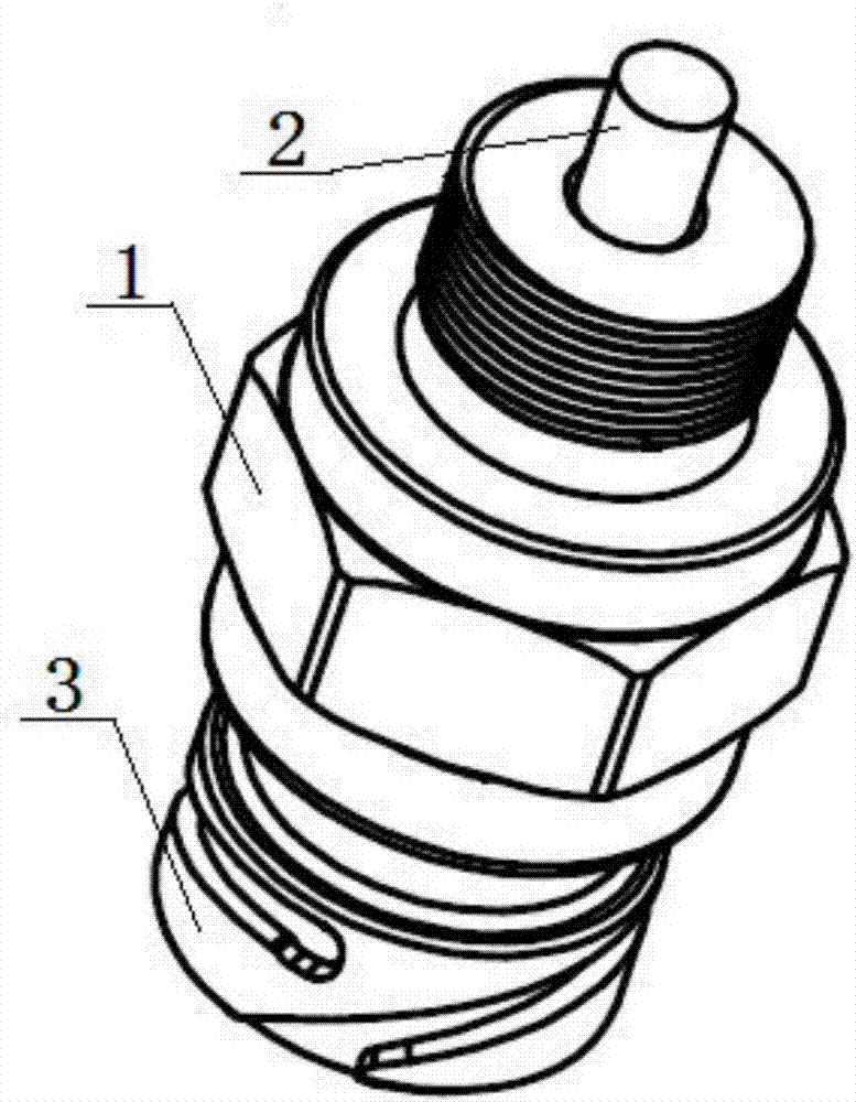
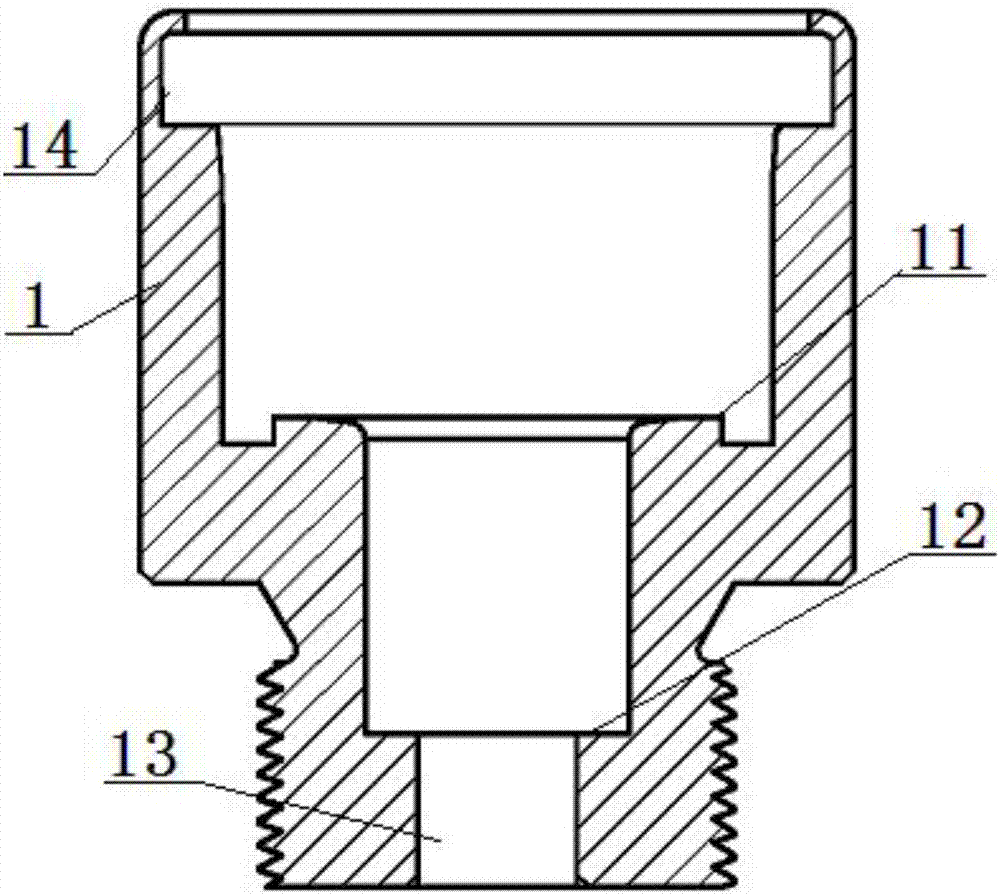
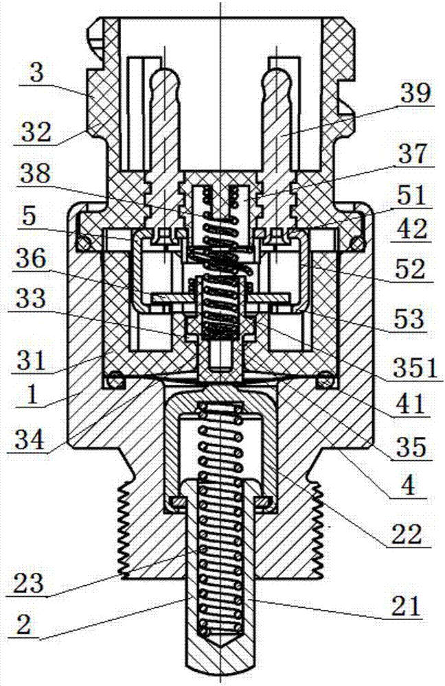
[0046] see Figure 1 to Figure 4 , an idle and reverse gear switch structure in a gearbox, comprising: a housing 1 and a feeler rod 2, the feeler rod 2 is arranged in the housing 1; the switch also includes a switch core 3, and the housing 1 There is a core mounting platform 11 inside, a stem mounting platform 12 is provided in the middle of the bottom surface of the core mounting platform 11, and a contact rod sliding hole 13 is provided in the middle of the bottom surface of the contact rod mounting platform 12, One end of the contact rod 2 is limitedly matched with the contact rod installation platform 12, and the other end of the contact rod 2 is slidably matched with the contact rod sliding hole 13; the lower end of the switch core 3 is fitted with the core component installation platform 11 The top of the switch core part 3 is tightly fitted, and the bottom surface of the switch core part 3 is sealed and matched with the core part installation platform 11 through the oil...

Embodiment 2

[0048] Embodiment 2 is basically the same as Embodiment 1, and its difference is:

[0049] see image 3 , the section of the static contact piece 5 is C-shaped, the static contact piece 5 includes an upper fixed piece 51, a middle contact piece 52 and a lower contact piece 53, the middle part of the upper fixed piece 51 is connected with the metal plug 39, The side of the upper fixed piece 51 is vertically connected to the upper end of the middle contact piece 52, the lower end of the middle contact piece 52 is vertically connected to the lower contact piece 53, and the metal movable contact piece 36 is arranged between the upper fixed piece 51 and the lower Between the contact pieces 53, the metal movable contact piece 36 is in contact with the lower contact pieces 53 on both sides respectively; the top of the contact button 35 is provided with a spring fixing hole 351, and one end of the contact piece spring 38 is arranged on the spring In the fixing hole 351 , the other en...

Embodiment 3

[0051] Embodiment 3 is basically the same as Embodiment 2, and its difference is:

[0052] see Figure 4 , the section of the static contact piece 5 is L-shaped, the static contact piece 5 includes an upper fixed piece 51 and a contact piece 54, the middle part of the upper fixed piece 51 is connected with the metal plug 39, and the upper fixed piece 51 The side portion of the contact piece 54 is vertically connected to the upper end of the contact piece 54, and the distance from the metal moving contact piece 36 to the bottom of the contact piece 54 is less than the maximum stroke of the touch button 35; the top of the touch button 35 is provided with a spring fixing rod 352, the One end of the contact spring 38 is set in the spring installation groove 37, and the other end of the contact spring 38 is sleeved on the spring fixing rod 352, and the bottom of the contact spring 38 is tightly fitted with the top surface of the metal movable contact 36. .


PUM


Abstract

Disclosed is a neutral gear and reverse gear switch structure in a gearbox. The neutral gear and reverse gear switch structure comprises a shell and a touch rod; the touch rod is arranged in the shell; the switch also comprises a switch core part; a core part mounting sinking table is arranged in the shell; a touch rod mounting sinking table is arranged in the middle part of the bottom surface of the core part mounting sinking table; a touch rod sliding hole is formed in the middle part of the bottom surface of the touch rod mounting sinking table; one end of the touch rod is matched with the touch rod mounting sinking table in a limiting manner while the other end of the touch rod is glidingly matched with the touch rod sliding hole; the lower end of the switch core part is matched with the top of the core part mounting sinking table in a tight clamping manner; and the bottom surface of the switch core part is matched with the core part mounting sinking table in a sealing manner through an oil-preventing membrane and a first sealing ring in sequence. The neutral gear and reverse gear switch structure is excellent in sealing property, capable of effectively preventing oil liquid from entering the switch, and high in durability and high in reliability.

Description

technical field [0001] The invention relates to a switch structure in a gearbox, in particular to an idle and reverse gear switch structure in a gearbox, which is particularly suitable for improving the oil-proof performance of the switch and improving the reliability of the switch. Background technique [0002] As GB7258-2012 "Technical Conditions for Motor Vehicle Operation Safety" stipulates that "motor vehicles using automatic transmissions shall be designed to ensure [The engine can also be started in the drive gear ("D" gear) when it has the automatic start-stop function]; When the "P" position is shifted into other gears, it should be completed by two actions of the driver in different directions." Therefore, the vehicle can only be started in neutral gear, and the existing neutral gear switch mostly adopts the seal ring to seal the switch push rod. The way to prevent the lubricating oil in the gearbox from entering the inside of the switch, but because the sealing r...

Claims


Application Information

Patent Timeline
Patent Type & Authority Applications(China)
IPC IPC(8): H01H13/06H01H13/26F16H63/42F16H63/50
CPCH01H13/06F16H63/42F16H63/50F16H2063/423H01H13/26
Inventor 陶玉容赵武程学文刘昶
Owner DONGFENG COMML VEHICLE CO LTD
Why Eureka
Try Eureka