Variable turn-on time control method of CRM fly-back PFC (Power Factor Correction) converter
A technology of varying on-time and on-time, used in control/regulation systems, conversion of DC power input to DC power output, instruments, etc. wave standard, difficulty in meeting harmonic requirements, etc.
- Summary
- Abstract
- Description
- Claims
- Application Information
AI Technical Summary
Problems solved by technology
Method used
Image

Examples
Embodiment 1
[0084] The present invention controls the variable conduction time of the CRM flyback PFC converter under the condition of fixed input
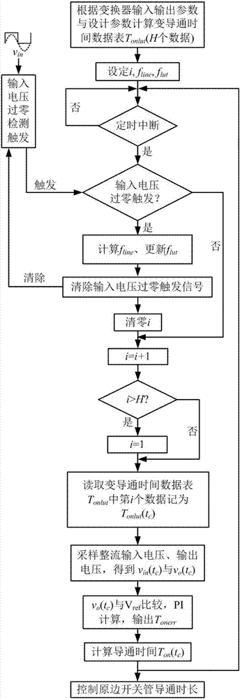
[0085] figure 1 It is the control flowchart of the variable conduction time of the CRM flyback PFC converter under the fixed input condition of the present invention. image 3 It is an embodiment of the variable on-time control method of the CRM flyback PFC converter proposed in the present invention under a fixed input condition.
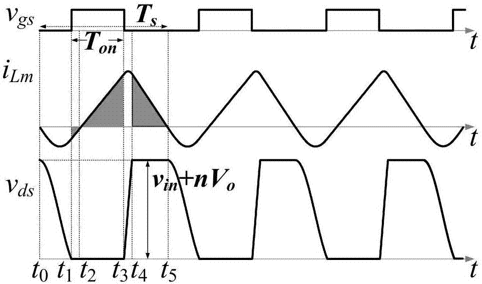
[0086] It is known that the input and output parameters of the CRM flyback PFC converter in this example are 220VAC / 50Hz, and the rated full-load power is P o =64W, output voltage V o =24V. It is known that the transformer primary side excitation inductance L of the CRM flyback PFC converter in this example m =300μH, the primary and secondary side turn ratio n=4, the primary side switching tube output junction capacitance C ds =313pF, secondary diode parasitic capacitance C j =50pF.
[0087] Select 101 mome...
Embodiment 2
[0106] The present invention controls the variable conduction time of the CRM flyback PFC converter under the general input condition
[0107] system
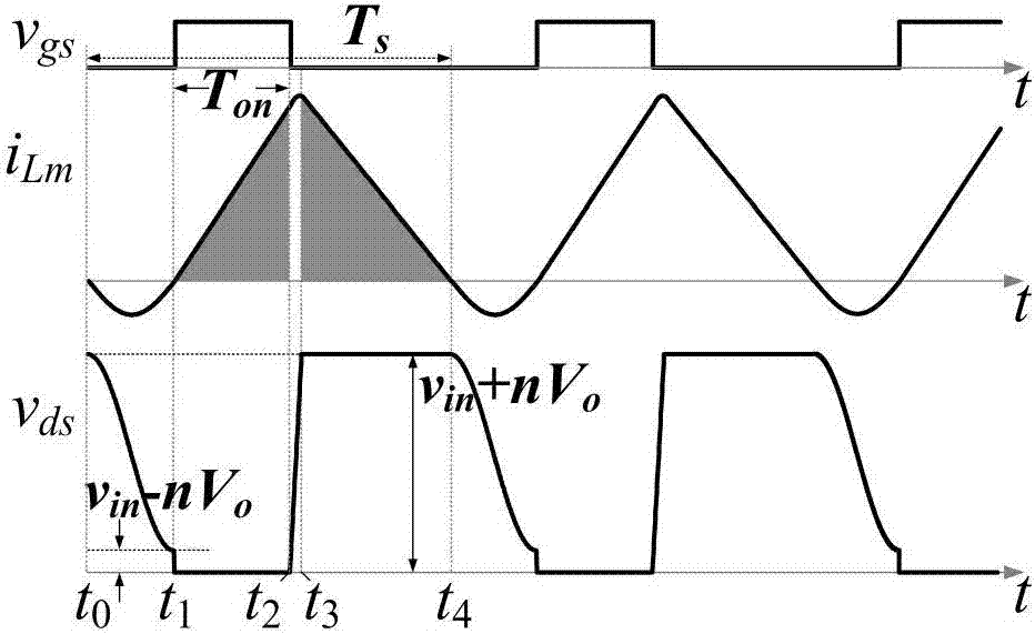
[0108] attached Figure 7 It is an embodiment of the variable on-time control method of the proposed CRM flyback PFC converter under the general input conditions (90-264VAC, 47Hz-63Hz). It is known that the input and output parameters of the CRM flyback PFC converter in this example are: 90V ~ 264VAC RMS input, 47Hz ~ 63Hz power frequency, output voltage V o =24V, rated full load power P o = 64W. In this example, the inductance value L of the magnetizing inductance of the primary side of the transformer is m =300μH, the primary and secondary side turn ratio n=4, the primary side switching tube output junction capacitance C ds =313pF, secondary diode parasitic capacitance C j =50pF.
[0109] In order to simplify the design, this example selects several RMS input line voltage calculations corresponding to the variable cond...
PUM
| Property | Measurement | Unit |
|---|---|---|
| Parasitic capacitance | aaaaa | aaaaa |
Abstract
Description
Claims
Application Information
 - R&D
- Intellectual Property
- Life Sciences
- Materials
- Tech Scout
- Unparalleled Data Quality
- Higher Quality Content
- 60% Fewer Hallucinations
Browse by: Latest US Patents, China's latest patents, Technical Efficacy Thesaurus, Application Domain, Technology Topic, Popular Technical Reports.
© 2025 PatSnap. All rights reserved.Legal|Privacy policy|Modern Slavery Act Transparency Statement|Sitemap|About US| Contact US: help@patsnap.com