A method of variable conduction time control for crm flyback pfc converter
A technology of changing on-time and on-time, which is applied in the control/regulation system, DC power input conversion to DC power output, instruments, etc. It can solve the problem of increasing input current THD and it is difficult for CRM flyback PFC converter to meet harmonic Wave standards, difficult to meet harmonic requirements and other issues
- Summary
- Abstract
- Description
- Claims
- Application Information
AI Technical Summary
Problems solved by technology
Method used
Image

Examples
Embodiment 1
[0083] The present invention controls the variable conduction time of the CRM flyback PFC converter under the condition of fixed input
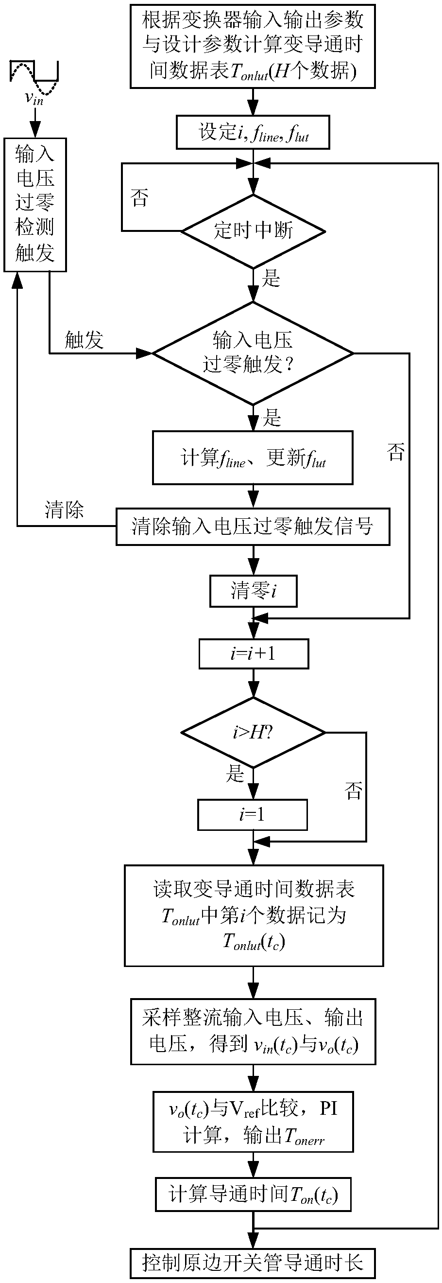
[0084] figure 1 It is the control flowchart of the variable conduction time of the CRM flyback PFC converter under the fixed input condition of the present invention. image 3 It is an embodiment of the variable on-time control method of the CRM flyback PFC converter proposed in the present invention under a fixed input condition.
[0085] It is known that the input and output parameters of the CRM flyback PFC converter in this example are 220VAC / 50Hz, and the rated full-load power is P o =64W, output voltage V o =24V. It is known that the transformer primary side excitation inductance L of the CRM flyback PFC converter in this example m =300μH, the primary and secondary side turn ratio n=4, the primary side switching tube output junction capacitance C ds =313pF, secondary diode parasitic capacitance C j =50pF.
[0086] Select 101 mome...
Embodiment 2
[0105] The present invention controls the variable conduction time of the CRM flyback PFC converter under the general input condition
[0106] attached Figure 9 It is an embodiment of the variable on-time control method of the proposed CRM flyback PFC converter under the general input conditions (90-264VAC, 47Hz-63Hz). It is known that the input and output parameters of the CRM flyback PFC converter in this example are: 90V ~ 264VAC RMS input, 47Hz ~ 63Hz power frequency, output voltage V o =24V, rated full load power P o = 64W. In this example, the inductance value L of the magnetizing inductance of the primary side of the transformer is m =300μH, the primary and secondary side turn ratio n=4, the primary side switching tube output junction capacitance C ds =313pF, secondary diode parasitic capacitance C j =50pF.
[0107] In order to simplify the design, this example selects several RMS input line voltage calculations corresponding to the variable conduction time data ...
PUM
 Abstract
Description
Claims
Application Information
 - R&D
- Intellectual Property
- Life Sciences
- Materials
- Tech Scout
- Unparalleled Data Quality
- Higher Quality Content
- 60% Fewer Hallucinations
Browse by: Latest US Patents, China's latest patents, Technical Efficacy Thesaurus, Application Domain, Technology Topic, Popular Technical Reports.
© 2025 PatSnap. All rights reserved.Legal|Privacy policy|Modern Slavery Act Transparency Statement|Sitemap|About US| Contact US: help@patsnap.com