Camera module testing method, camera module testing device and computer readable storage medium

A technology of a camera module and a test method, applied in the field of photography, can solve the problem of the attenuation of the resolution of the camera module, and achieve the effect of reducing the degree of attenuation

Active Publication Date: 2017-09-08
GUANGDONG OPPO MOBILE TELECOMM CORP LTD
View PDF10 Cites 9 Cited by
  • Summary
  • Abstract
  • Description
  • Claims
  • Application Information

AI Technical Summary

Problems solved by technology

[0004] Usually, a camera module includes components such as a lens module and a lens holder. When the camera module is assembled on an electronic device, the position of the lens module of the camera module in the mirror holder will change due to the extrusion of the housing of the electronic device. Offset, which eventually causes the resolution of the camera module to be seriously attenuated

Method used


Image

  • Camera module testing method, camera module testing device and computer readable storage medium
  • Camera module testing method, camera module testing device and computer readable storage medium
  • Camera module testing method, camera module testing device and computer readable storage medium

Examples


Embodiment 2

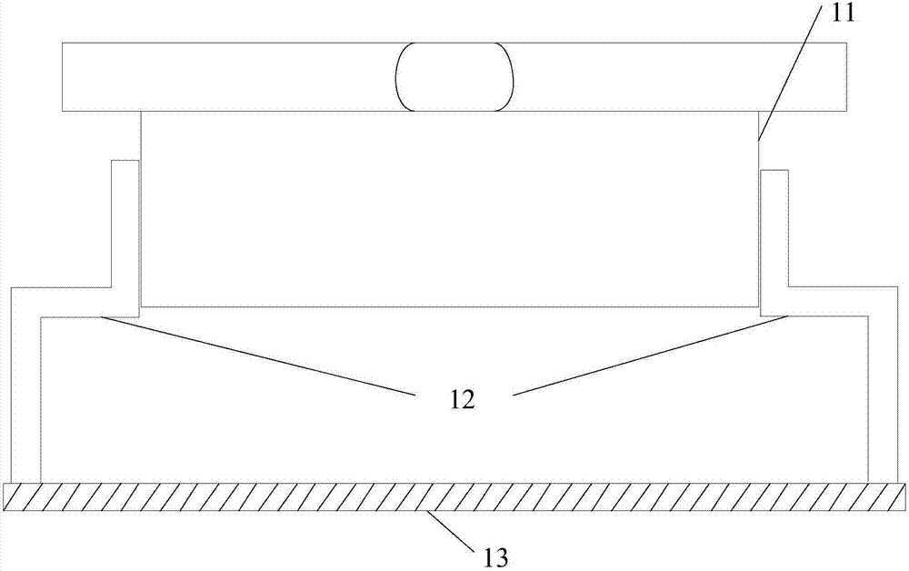
[0067] The embodiment of the present invention also provides a test device for a camera module, the camera module includes: a lens module and a lens holder for arranging the above-mentioned lens module, specifically, the structure of the camera module can be referred to Figure 1-a The description in the illustrated embodiment will not be repeated here. Such as image 3 As shown, the test device 300 of the camera module in the embodiment of the present invention includes:

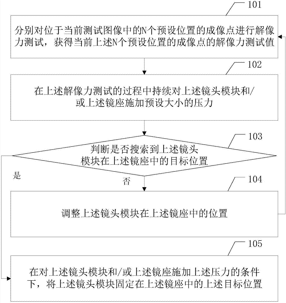
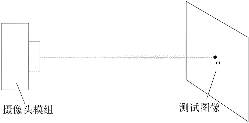
[0068] The resolution test unit 301 is configured to respectively perform a resolution test on the imaging points at N preset positions in the current test image, and obtain the current resolution test values ​​of the imaging points at the N preset positions, wherein the current test image is determined by the current test image. The camera module is formed, and the above N is greater than or equal to 1;

[0069] The pressure applying unit 302 is configured to continuously apply a predetermined amount of p...

Embodiment 3

[0078] An embodiment of the present invention provides another testing device for a camera module, the camera module includes: a lens module and a lens holder for arranging the above-mentioned lens module, specifically, the structure of the camera module can be referred to Figure 1-a The description in the illustrated embodiment will not be repeated here. Such as Figure 4 As shown, the test device 400 of the camera module in the embodiment of the present invention includes: a memory 401, one or more processors 402 ( Figure 4 Only one of them is shown) and a computer program stored on the memory 401 and executable on the processor. Wherein: the memory 401 is used to store software programs and modules, and the processor 402 executes various functional applications and data processing by running the software programs and units stored in the memory 401 . Specifically, the processor 402 implements the following steps by running the above-mentioned computer program stored in th...


PUM


Abstract

The invention discloses a camera module testing method, a camera module testing device and a computer readable storage medium, wherein the camera module testing method comprises the steps of: respectively performing resolution power testing of imaging points of N pre-set positions in a current test image; continuously applying pre-set pressure on the lens and / or the holder of a camera assembly in a resolution power testing process; adjusting the position of the lens in the holder, and returning to the resolution power testing step and the subsequent step till the target position of the lens in the holder is searched, wherein when the lens is at the target position in the holder, the resolution power testing value of the imaging point at the pre-set position in the N pre-set positions is maximum; and fixing the lens at the target position in the holder when the target position is searched. By means of the technical scheme provided by the invention, the resolution power attenuation degree of a camera module after being assembled on electronic equipment can be effectively reduced.

Description

technical field [0001] The present invention relates to the field of camera technology, in particular to a camera module testing method, device and computer-readable storage medium. Background technique [0002] With the rapid development of intelligence in the electronic technology industry, the camera system used to acquire image and video information, as the carrier of human visual extension, has gradually become a core device and is widely used in various electronic devices. [0003] At present, more and more electronic devices are beginning to develop in the direction of miniaturization, miniaturization and high image quality. Based on this trend, camera devices are also miniaturized into camera modules to be installed in electronic devices. [0004] Usually, a camera module includes components such as a lens module and a lens holder. When the camera module is assembled on an electronic device, the position of the lens module of the camera module in the mirror holder wi...

Claims


Application Information

Patent Timeline
IPC IPC(8): H04N17/00
CPCH04N17/002
Inventor 熊国访
Owner GUANGDONG OPPO MOBILE TELECOMM CORP LTD
Why Eureka
Try Eureka