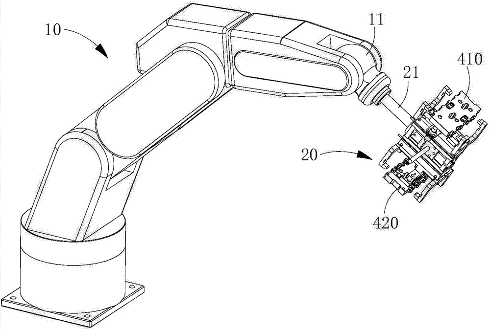
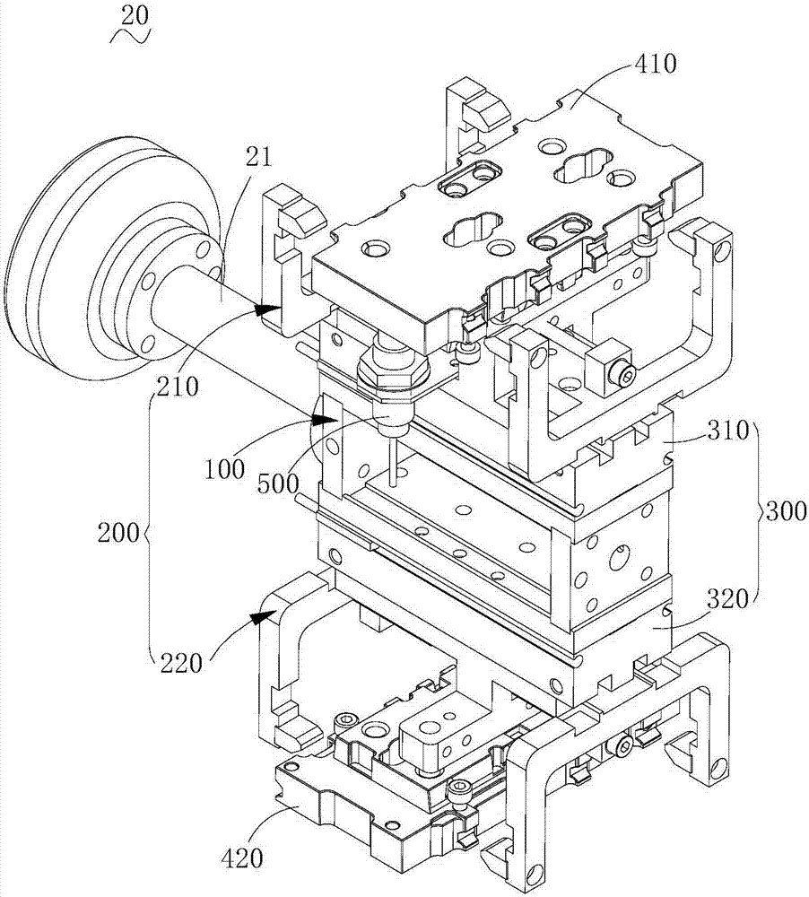
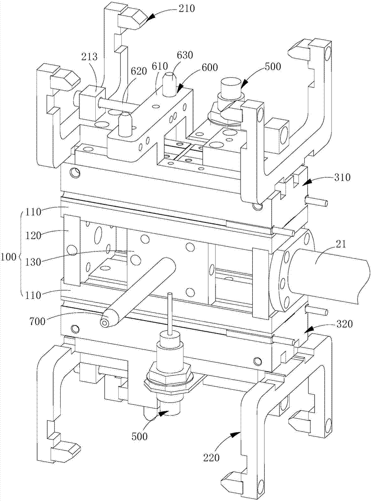
Manipulator

A technology of manipulators and machine tools, applied in the field of manipulators, can solve problems such as low efficiency, easy to cause work-related injuries, and low operating precision

Inactive Publication Date: 2017-09-12
GUANGDONG TIANJI IND INTELLIGENT SYST CO LTD
View PDF9 Cites 16 Cited by
  • Summary
  • Abstract
  • Description
  • Claims
  • Application Information

AI Technical Summary

Problems solved by technology

For example, in the processing of mobile phone cases, the mobile phone case to be processed is placed on a CNC machine tool for processing. The existing loading and unloa

Method used


Image

  • Manipulator
  • Manipulator
  • Manipulator

Examples


Embodiment Construction

[0024] In order to facilitate the understanding of the present invention, the present invention will be described more fully below with reference to the associated drawings. Preferred embodiments of the invention are shown in the accompanying drawings. However, the present invention can be embodied in many different forms and is not limited to the embodiments described herein. On the contrary, the purpose of providing these embodiments is to make the disclosure of the present invention more thorough and comprehensive.

[0025] It should be noted that when an element is considered to be "connected" to another element, it may be directly connected to the other element or there may be intervening elements at the same time. The terms "vertical," "horizontal," "left," "right," and similar expressions are used herein for purposes of illustration only and are not intended to represent the only embodiments.

[0026] Unless otherwise defined, all technical and scientific terms used h...


PUM


Abstract

The invention relates to a manipulator, comprising: a fixed seat; two claws, symmetrically arranged on the opposite side walls of the fixed seat, and one of the two claws is used for grabbing from a jig The workpiece to the machine tool, and the other jaw is used to grab the workpiece processed on the machine tool and place it on the fixture or the external workpiece collection place; the driving mechanism is arranged on the fixed seat and connected with the two jaws to Drive the opening and closing of the two claws. The above-mentioned manipulator is equipped with two jaws, one jaw is used for loading and the other jaw is used for unloading, which can be used for fast loading and unloading in actual processing. high.

Description

technical field [0001] The invention relates to the technical field of machining, in particular to a manipulator. Background technique [0002] With the rapid development of electronics and information technology, industrial processing is increasingly moving towards high-speed development. For example, in the processing of mobile phone cases, the mobile phone case to be processed is placed on a CNC machine tool for processing. The existing loading and unloading operations are mostly done manually. The operation accuracy is low, the efficiency is low, and the working environment is harsh Poor, prone to work-related injuries. Contents of the invention [0003] Based on this, it is necessary to provide a safe, reliable and highly efficient manipulator. [0004] A manipulator comprising: [0005] Fixing seat for connecting with the free end of the robot; [0006] Two claws are symmetrically arranged on the opposite side walls of the fixed seat, one of the two claws is used...

Claims


Application Information

Patent Timeline
IPC IPC(8): B23Q7/04B25J15/08
CPCB23Q7/048B23Q7/008B25J15/08
Inventor 雷冬生
Owner GUANGDONG TIANJI IND INTELLIGENT SYST CO LTD
Why Eureka
Try Eureka