Viscous damper with hydraulic fusing function

A viscous damper and fusing technology, applied in the field of viscous dampers, can solve the problems of high maintenance cost and low efficiency, and achieve the effect of low maintenance cost and high work efficiency

Active Publication Date: 2017-09-12
ZHUZHOU TIMES NEW MATERIALS TECH
View PDF7 Cites 12 Cited by
  • Summary
  • Abstract
  • Description
  • Claims
  • Application Information

AI Technical Summary

Problems solved by technology

However, once the metal fuse breaks, it needs to be replac

Method used


Image

  • Viscous damper with hydraulic fusing function
  • Viscous damper with hydraulic fusing function
  • Viscous damper with hydraulic fusing function

Examples


Example Embodiment

[0027] The present invention will be further described in detail below with reference to the accompanying drawings and specific embodiments, but the protection scope of the present invention is not limited thereby.
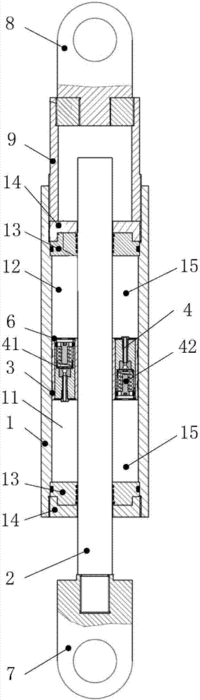
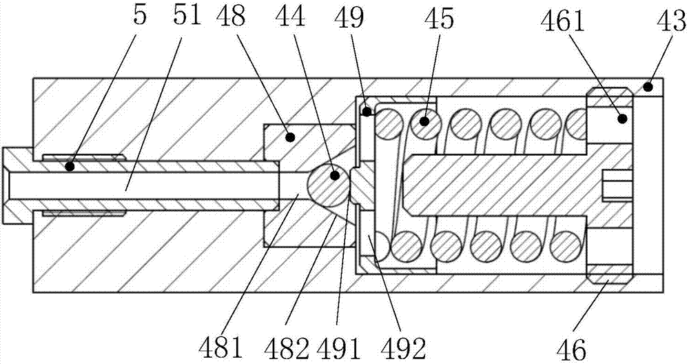
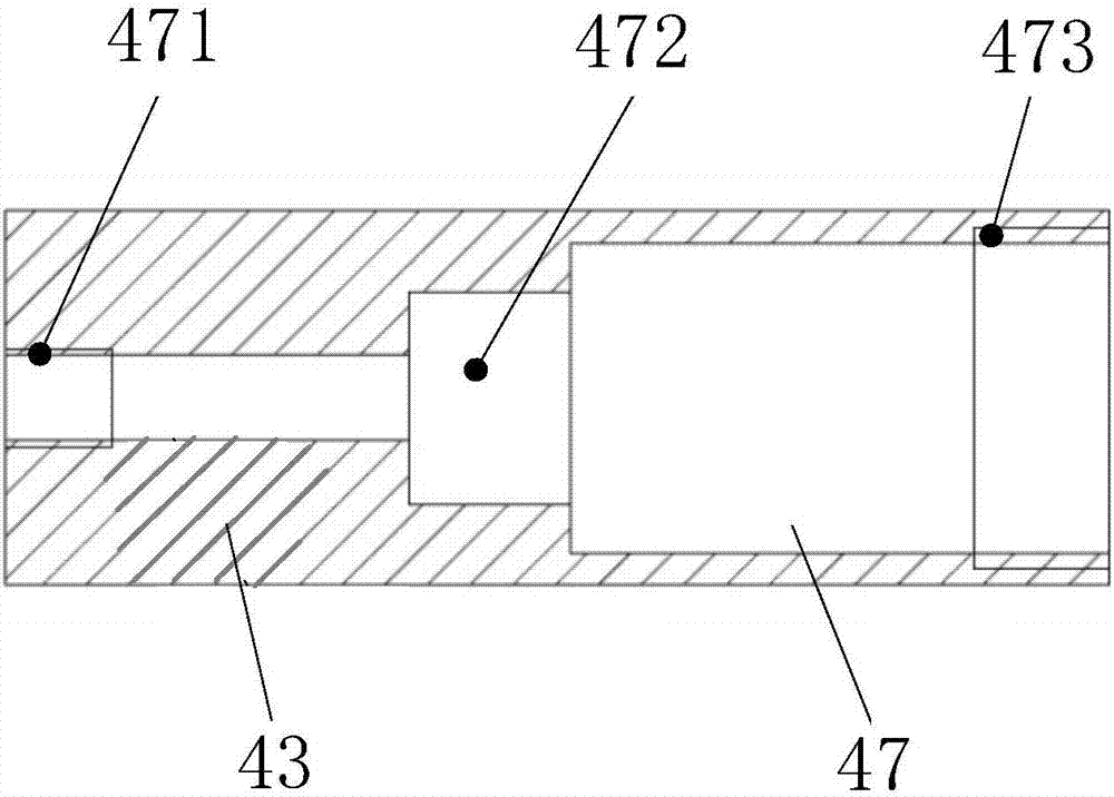
[0028] like Figure 1 to Figure 3 An embodiment of the viscous damper with hydraulic fuse function of the present invention is shown. The viscous damper with hydraulic fuse function is suitable for the partial vibration isolation control field of bridge construction. The viscous damper does not undergo relative displacement when the load is high, and the viscous damper is required to absorb energy and reduce vibration to ensure the safety of the structure in the event of strong winds, large earthquakes or exceeding a certain dynamic load. In this embodiment, the viscous damper with hydraulic fuse function includes a cylinder 1, a piston rod 2 and a piston 3. The piston 3 is installed in the cylinder 1 and divides the cylinder 1 into a variable size and a constant ...


PUM


Abstract

The invention provides a viscous damper with a hydraulic fusing function. The viscous damper comprises a cylinder, a piston rod and a piston; the piston is mounted in the cylinder for dividing the cylinder into a first cavity and a second cavity; viscous mediums are filled in the first cavity and the second cavity; and the piston is provided with a first one-way valve for allowing the viscous mediums to flow from the first cavity to the second cavity and a second one-way valve for allowing the viscous medium to flow from the second cavity to the first cavity. The viscous damper has the advantages of high working efficiency and low maintenance cost.

Description

technical field [0001] The invention relates to the technical field of shock absorption (vibration), in particular to a viscous damper with hydraulic fusing function. Background technique [0002] In the 1970s, viscous dampers were gradually introduced into the field of anti-seismic engineering such as buildings and bridges. Due to their simple structure, low cost, and obvious shock-absorbing effect, they have been widely used. Conventional viscous dampers generally adopt a hydraulic cylinder structure. It is mainly composed of piston, piston rod, cylinder, viscous liquid and sealing system. The piston divides the cylinder into two chambers, which are filled with viscous liquid. The two chambers can exchange flow through damping holes or gaps. When the viscous damper is in the working state, the piston rod drives the piston to move, so that the two chambers form a pressure difference, thereby forcing the viscous medium from the high-pressure chamber to the low-pressure cham...

Claims


Application Information

Patent Timeline
IPC IPC(8): F16F9/53F16F9/34F16F9/36
Inventor 文登唐璐孙湘民韩鹏飞袁可刘军郭红锋
Owner ZHUZHOU TIMES NEW MATERIALS TECH
Why Eureka
Try Eureka