Air cooling tower and indirect air cooling system

An air-cooling tower and tower body technology, which is applied in the field of thermal power generation equipment, can solve the problems of reduced air flow, affecting heat exchange effect, and weakened heat exchange capacity.

Pending Publication Date: 2017-09-12
GUODIAN SCI & TECH RES INST
View PDF5 Cites 10 Cited by
  • Summary
  • Abstract
  • Description
  • Claims
  • Application Information

AI Technical Summary

Problems solved by technology

[0003] When working, in the state of static wind, the ambient air flows in horizontally. After being heated by the radiator, it turns upwards in the air cooling tower, and a negative pressure backflow phenomenon will appear near the concrete wall within a certain height of the air inlet of the air cooling tower, forming a local flow. The dead zone leads to high air temperature in this area, which will affect the heat exchange effect over time; in the state of ambient wind, the windward and leeward sides of the air-cooling tower have uneven air intake, and the pressure on the windward side of the air-cooling tower increases and the pressure on the leeward side decreases. , are prone to backflow phenomen

Method used


Image

  • Air cooling tower and indirect air cooling system
  • Air cooling tower and indirect air cooling system
  • Air cooling tower and indirect air cooling system

Examples


Embodiment Construction

[0025] The invention provides an air-cooling tower and an indirect air-cooling system to achieve the purpose of eliminating flow dead zone, weakening the adverse influence of ambient wind and improving heat exchange effect.

[0026] The following will clearly and completely describe the technical solutions in the embodiments of the present invention with reference to the accompanying drawings in the embodiments of the present invention. Obviously, the described embodiments are only some, not all, embodiments of the present invention. Based on the embodiments of the present invention, all other embodiments obtained by persons of ordinary skill in the art without making creative efforts belong to the protection scope of the present invention.

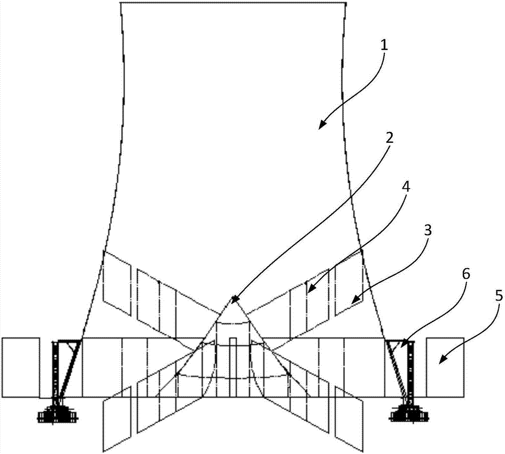
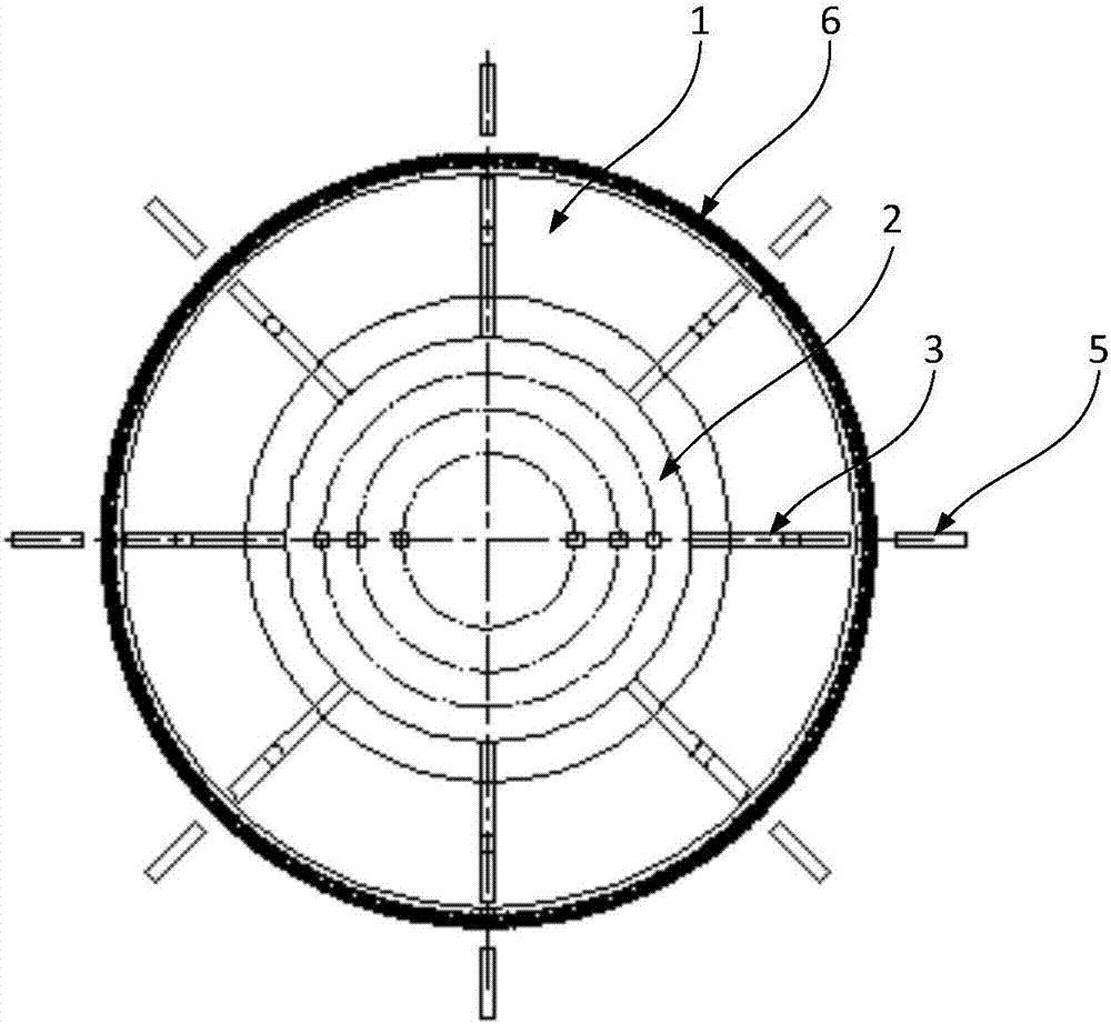
[0027] see figure 1 and figure 2 , figure 1 The front view of the air cooling tower provided by the embodiment of the present invention, figure 2 The top view of the air cooling tower provided by the embodiment of the present inventi...


PUM


Abstract

The invention discloses an air cooling tower. The air cooling tower comprises a tower body and a flow guiding device; the flow guiding device comprises a central flow guiding part and flow guiding plates, the central flow guiding part is arranged at the center of the bottom of the tower body, a flow guiding face is formed in the circumferential direction of the central flow guiding part, the flow guiding plates comprise eight inner flow guiding plates and eight outer flow guiding plates, the eight inner flow guiding plates are connected to the flow guiding face of the central flow guiding part in the circumferential direction in an evenly-distributed mode, the eight outer flow guiding plates and the eight inner flow guiding plates are arranged outside the tower body in a one-to-one correspondence mode in the circumferential direction, and channels communicating with the flow guiding face are formed between every two adjacent outer flow guiding plates and between every two adjacent inner flow guiding plates. According to the air cooling tower, by additionally arranging the flow guiding device, wind field energy can be reasonably utilized, the ventilation quantity in the air cooling tower can be increased, influences of a negative pressure zone on an air flow field can be reduced, and then adverse effects of environmental wind on running of an indirect air cooling system and the heat exchange performance of an air cooling radiator are weakened. The invention further discloses the indirect air cooling system.

Description

technical field [0001] The invention relates to the technical field of thermal power generation equipment, in particular to an air cooling tower and an indirect air cooling system. Background technique [0002] The indirect air cooling system is a system that uses ambient air as the cold source and closed circulating water as the intermediate medium to transfer the heat of the exhaust steam of the steam turbine to the circulating water, and the closed circulating water is transferred to the atmosphere through the air-cooled radiator, mainly including condensing steam The air cooling tower consists of a tower body and an air cooling radiator. The condenser, the circulating water pump and the radiator are connected in series to form a circulating water loop. The circulating water heated in the condenser is pumped by the circulating water. To the air-cooled radiator, heat exchange with the air in the air-cooled radiator, the cooled circulating water returns to the condenser to ...

Claims


Application Information

Patent Timeline
IPC IPC(8): F28C1/00F28F25/12
CPCF28C1/00F28F25/12F28C2001/006
Inventor 曹蓉秀冯云鹏陈阳张华峰张伟史鹏飞王兴
Owner GUODIAN SCI & TECH RES INST
Why Eureka
Try Eureka