
Mechanical property testing device for micrometer monofilament fiber

A monofilament fiber, testing device technology, applied in measuring devices, using stable tension/pressure to test material strength, scientific instruments, etc., can solve the problem of long glue drop cycle, long sample preparation cycle, and difficult to control glue drop size problem, to achieve the effect of improving accuracy and efficiency, and simple structure

Active Publication Date: 2017-09-12
SHAANXI UNIV OF SCI & TECH
View PDF6 Cites 0 Cited by
  • Summary
  • Abstract
  • Description
  • Claims
  • Application Information

AI Technical Summary

Problems solved by technology

Manual sample preparation has the disadvantages of long bead cycle, difficult control of bead size, and easy pulling of fibers from bead during stretching
[0003] In summary, how to solve the problems of long sample preparation period, easy fiber damage, low test efficiency and complex structure in the process of testing the tensile mechanical properties of monofilament fibers has become an urgent problem in this field.

Method used


Image

  • Mechanical property testing device for micrometer monofilament fiber
  • Mechanical property testing device for micrometer monofilament fiber
  • Mechanical property testing device for micrometer monofilament fiber

Examples


Embodiment Construction

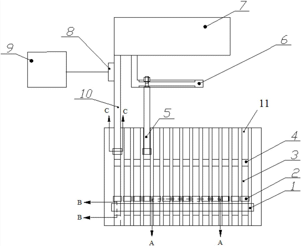
[0025] In order to enable those skilled in the art to better understand the structure and working principle of the present invention, the present invention will be further described below in conjunction with the accompanying drawings.

[0026] The orientation or positional relationship indicated by the terms "upper", "lower", "front", "rear", "left", "right", "top", "bottom", "inner", "outer" etc. are based on the attached The orientation or positional relationship shown in the figure is only for the convenience of describing the present invention and simplifying the description, and does not indicate or imply that the referred device or element must have a specific orientation, be constructed and operated in a specific orientation, and therefore cannot be construed as a reference to this invention. The limitation of the invention, in the following narration, the direction where the fader is located is the front, and the direction where the linear motor is located is the rear. ...


PUM


Abstract

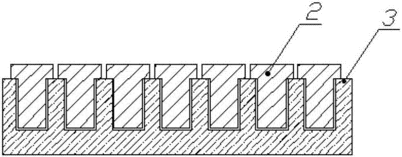
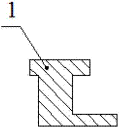
The invention discloses a mechanical property testing device for a micrometer monofilament fiber. The mechanical property testing device comprises a bottom plate, wherein a plurality of grooves are arranged on the bottom plate in parallel; slide blocks and clamp heads are sequentially arranged on the bottom plate from front to back, and are matched with the grooves; the multiple slide blocks are inserted into the grooves to form a row, and can slide in the grooves; the clamp heads comprise first clamp heads and second clamp heads, and the side surface, near one side of each slide block, of each of the first clamp heads and second clamp heads is flush, and is respectively inserted into the corresponding groove; each first clamp head is horizontally moved, the surface of each second clamp head is attached with a strain sensor, and each strain sensor is connected with a mechanical recorder. The mechanical property testing device has the advantages that by adopting the semi-automatic positioning and automatic clamping units, the length of the monofilament fiber can be adjusted, the advanced sample preparation is not needed, and the structure is simple; the testing accuracy and efficiency of the monofilament fiber are improved.

Description

technical field [0001] The invention belongs to the technical field of fiber mechanical performance testing equipment, and in particular relates to a mechanical performance testing device for micron-sized monofilament fibers. Background technique [0002] Existing devices for testing the tensile mechanical properties of monofilament fibers mainly include: the first type of device adopts the paper sheet method for sample preparation, and is not clamped by automatic machinery. The sample preparation period of the paper method is long, and the fibers need to be manually positioned during the sample preparation process, which is easy to be damaged; when clamping, manual clamping is required, which is inefficient; the second type of device uses the paper method for sample preparation, and is clamped by a pneumatic chuck. The pneumatic chuck has the advantages of controllable clamping force and less damage to the fiber, but the pneumatic clamping device requires an air source and ...

Claims


Application Information

Patent Timeline
IPC IPC(8): G01N3/02G01N3/04G01N3/08
CPCG01N3/02G01N3/04G01N3/08G01N2203/0017
Inventor 赵雪妮孙秀丽王旭东张黎张靖王婉英杨建军何富珍
Owner SHAANXI UNIV OF SCI & TECH
Learn More