Backlight module and liquid crystal display device

A backlight module and liquid crystal panel technology, applied in optics, nonlinear optics, instruments, etc., can solve problems such as cost reduction of backlight, achieve the effect of reducing backlight cost, reducing optical film, and increasing light mixing distance

Inactive Publication Date: 2017-09-12
TCL CHINA STAR OPTOELECTRONICS TECH CO LTD
View PDF13 Cites 3 Cited by
  • Summary
  • Abstract
  • Description
  • Claims
  • Application Information

AI Technical Summary

Problems solved by technology

[0005] It can be seen that the existing backlight modules all need an optical film to improve the brightness and uniformity of the light source 11, but the setting of the optical film is not conducive to the reduction of the cost of the backlight

Method used


Image

  • Backlight module and liquid crystal display device
  • Backlight module and liquid crystal display device
  • Backlight module and liquid crystal display device

Examples


Embodiment Construction

[0014] The following will clearly and completely describe the technical solutions of each exemplary embodiment provided by the present invention with reference to the accompanying drawings in the embodiments of the present invention. In the case of no conflict, the following embodiments and the technical features of the present invention can be combined with each other. Moreover, the directional terms used throughout the present invention, such as "left", "right", etc., are for better describing various embodiments, and are not used to limit the protection scope of the present invention.

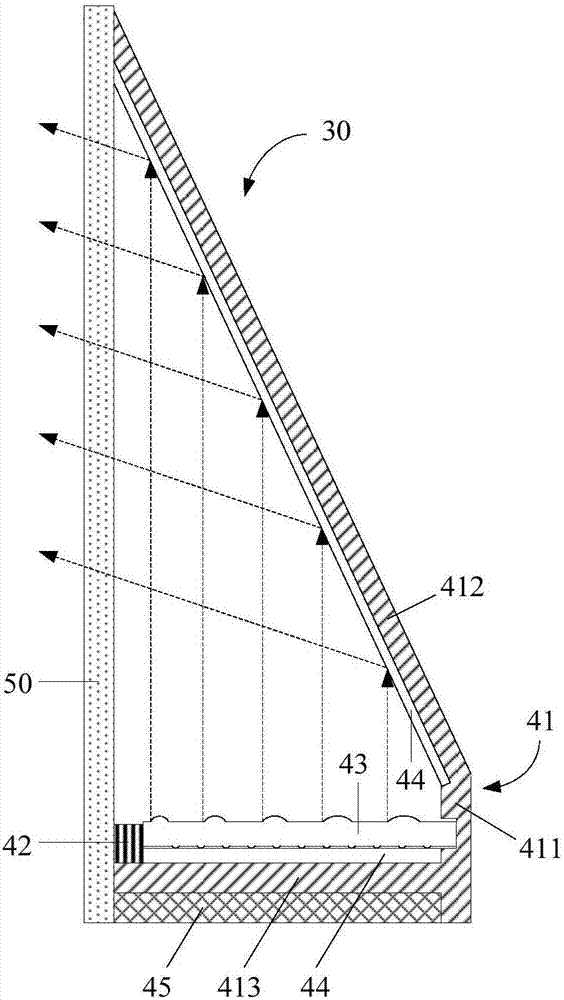
[0015] see image 3 , is a liquid crystal display device according to an embodiment of the present invention. The liquid crystal display device 30 includes a backlight module and a liquid crystal panel 50 arranged on the light emitting direction of the backlight module. 41 on the light source 42, light guide plate 43, reflector 44.

[0016] The backboard 41 includes a vertical plate body ...


PUM


Abstract

The invention discloses a backlight module and a liquid crystal display device. A backplate of the backlight module comprises a vertical plate body and an inclined plate body in an obtuse angle arrangement, wherein the vertical plate body and a liquid crystal display panel are distantly arranged in parallel; a light-guiding plate and a light source are arranged between the vertical plate body and the liquid crystal display panel; a reflective plate is arranged on the inner side of the inclined plate body; a plurality of lens and a plurality of dots are arranged on the emergent surface and the bottom surface of the light-guiding plate respectively. On the basis of the invention, an optical diaphragm for backlighting can be reduced and reduction in the backlighting cost is facilitated.

Description

technical field [0001] The invention relates to the display field, in particular to a backlight module and a liquid crystal display device. Background technique [0002] The backlight module (Backlight Module) of LCD (Liquid Crystal Display, liquid crystal display device) includes two kinds of light incident methods, which are side light type and direct light type. [0003] Such as figure 1 As shown, in the structural design of the side-illuminated backlight module, the light source 11 is arranged on the side of the light guide plate 12, and the light emitted by the light source 11 enters the light guide plate 12 from the light incident surface of the light guide plate 12, and passes through the After diffuse reflection, it emits from the light-emitting surface, and then passes through various optical films 13 , such as diffusion sheets and prism sheets, to form a uniform surface light source and provide it to the liquid crystal panel 14 . [0004] Such as figure 2 As sh...

Claims


Application Information

Patent Timeline
Patent Type & Authority Applications(China)
IPC IPC(8): G02F1/13357
CPCG02F1/133605G02F1/133606G02F1/133608G02F1/133607
Inventor 樊勇
Owner TCL CHINA STAR OPTOELECTRONICS TECH CO LTD
Why Eureka
Try Eureka