Method for analyzing and calculating magnetic leakage coefficient of built-in permanent magnet synchronous motor

A technology of permanent magnet synchronous motor and flux leakage coefficient, applied in calculation, electrical digital data processing, design optimization/simulation, etc., can solve the problems of long data preparation time, not widely used, not easy to integrate, etc., and achieve accurate calculation , the effect of improving accuracy

Inactive Publication Date: 2017-09-12
SHANDONG UNIV
View PDF5 Cites 11 Cited by
  • Summary
  • Abstract
  • Description
  • Claims
  • Application Information

AI Technical Summary

Problems solved by technology

At present, the accurate calculation of the flux leakage coefficient mainly adopts the finite element method. Since the application of the finite element method in enterprises is not yet widespread, designers often estimate the flux leakage coefficient based on experience, which greatly reduces the accuracy of electromagnetic calculations.
[0004] In addition, the flux leakage coefficient can be accurately calculated using the finite element method, but the data preparation time is long, and it is not easy to integrate it into the electromagnetic calculation using the magnetic circuit analysis method

Method used


Image

  • Method for analyzing and calculating magnetic leakage coefficient of built-in permanent magnet synchronous motor
  • Method for analyzing and calculating magnetic leakage coefficient of built-in permanent magnet synchronous motor
  • Method for analyzing and calculating magnetic leakage coefficient of built-in permanent magnet synchronous motor

Examples


Embodiment Construction

[0020] The present invention will be further described below in conjunction with the accompanying drawings and embodiments.

[0021] It should be pointed out that the following detailed description is exemplary and intended to provide further explanation to the present application. Unless defined otherwise, all technical and scientific terms used herein have the same meaning as commonly understood by one of ordinary skill in the art to which this application belongs.

[0022] It should be noted that the terminology used here is only for describing specific implementations, and is not intended to limit the exemplary implementations according to the present application. As used herein, unless the context clearly dictates otherwise, the singular is intended to include the plural, and it should also be understood that when the terms "comprising" and / or "comprising" are used in this specification, they mean There are features, steps, operations, means, components and / or combinatio...


PUM


Abstract

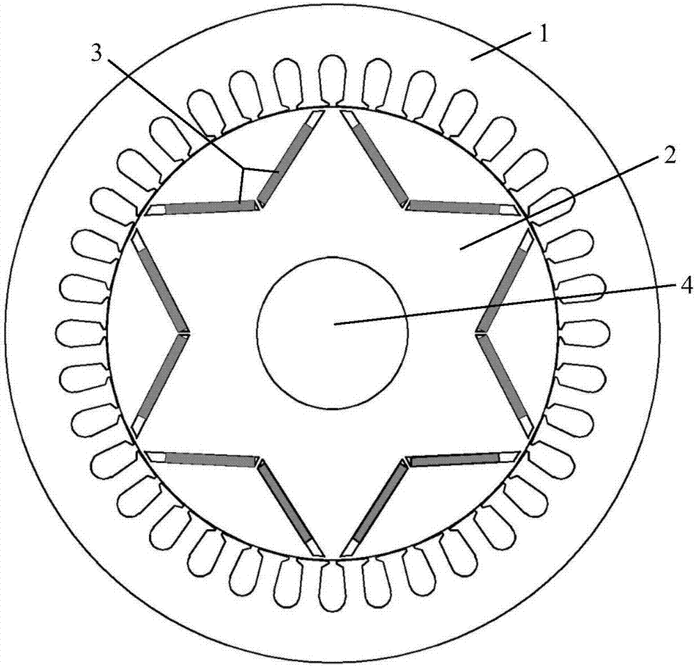
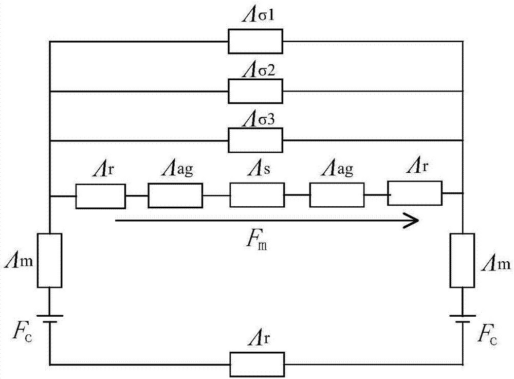
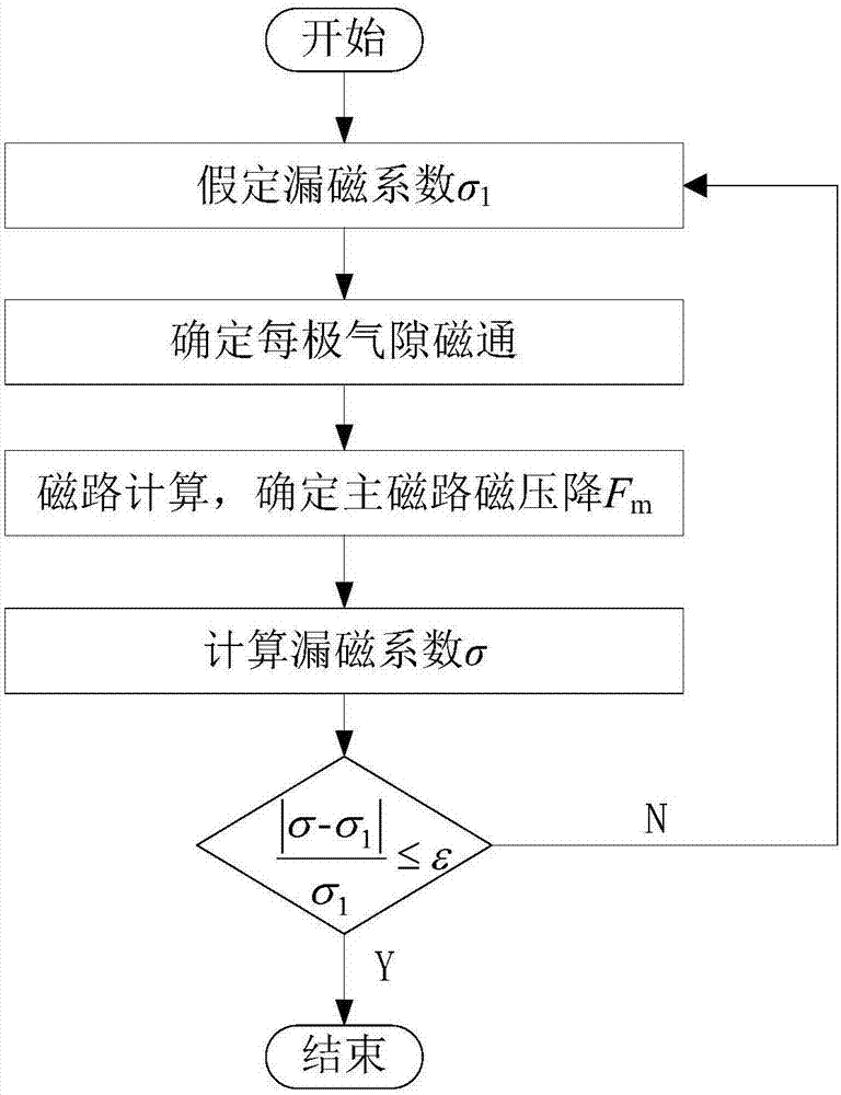
The invention discloses a method for analyzing and calculating magnetic leakage coefficient of a built-in permanent magnet synchronous motor. The method comprises the following steps: supposing a value of the magnetic leakage coefficient, determining main magnetic flux of each electrode, and calculating the magnetic pressure drop of a main magnetic path based on the magnetic pressure drop of the main magnetic path, wherein the magnetic pressure drop is magnetic pressure drop added on the magnetic leakage path and a magnetic bridge part has high magnetic resistance, so the magnetic pressure drop is mainly added on the magnetic bridge part, and the magnetic field intensity of the magnetic bridge part can be determined; searching a magnetization curve according to the obtained magnetic field intensity of the magnetic bridge part to obtain the magnetic flux density of the magnetic bridge part, calculating the magnetic leakage flux, and evaluating the magnetic leakage coefficient according all the magnetic leakage flux; if the difference between the magnetic leakage coefficient and the supposed value exceeds a threshold value, resetting the magnetic leakage coefficient and repeating the above calculation process; if the difference value between the calculated value and the supposed value is within an allowable error threshold value, the calculated value is the obtained magnetic leakage coefficient. By the method, the magnetic leakage coefficient of the built-in permanent magnet motor can be calculated accurately and can be conveniently integrated into electromagnetic calculation adopting a magnetic path analysis method, and the accuracy of electromagnetic calculation is improved.

Description

technical field [0001] The invention relates to an analytical calculation method for the flux leakage coefficient of a built-in permanent magnet synchronous motor. Background technique [0002] In a permanent magnet motor, the magnetic flux generated by each pole permanent magnet is divided into two parts: main flux and leakage flux. The ratio of the magnetic flux generated by each pole permanent magnet to the main flux is called the leakage coefficient. Flux leakage coefficient is a key parameter in the design of permanent magnet synchronous motor, which is very important to the accuracy of electromagnetic calculation of the motor. [0003] For the built-in permanent magnet synchronous motor, since the permanent magnet is built inside the rotor, the distribution of the magnetic flux leakage is complex, and the magnetic flux leakage coefficient is greatly affected by the structure size. At present, the accurate calculation of the magnetic flux leakage coefficient mainly ado...

Claims


Application Information

Patent Timeline
Patent Type & Authority Applications(China)
IPC IPC(8): G06F17/50
CPCG06F30/20
Inventor 王秀和徐定旺
Owner SHANDONG UNIV
Why Eureka
Try Eureka