Pressing-type self-locking pull head

A push-type, self-locking technology, applied in the direction of sliding fastener components, applications, fasteners, etc., can solve the problems of shortening the service life of self-locking sliders, easy damage of shrapnel and horse hooks, unfavorable assembly, etc., to achieve operational use Simple and flexible, flexible self-locking or unlocking, convenient and quick assembly

Active Publication Date: 2017-09-15
FUJIAN SBS ZIPPER SCI & TECH CO LTD
View PDF6 Cites 9 Cited by
  • Summary
  • Abstract
  • Description
  • Claims
  • Application Information

AI Technical Summary

Problems solved by technology

This kind of slider that relies on the mutual cooperation of the horse hook and the shrapnel to realize self-locking has the following defects: First, the existing self-locking slider has a relatively complicated structure, which makes the assembly process of the slider more cumbersome and complicated, which is not conducive to It is convenient and quick to assemble; s

Method used


Image

  • Pressing-type self-locking pull head
  • Pressing-type self-locking pull head
  • Pressing-type self-locking pull head

Examples


Example Embodiment

[0016] The preferred embodiments of the present invention will be described in detail below with reference to the accompanying drawings.

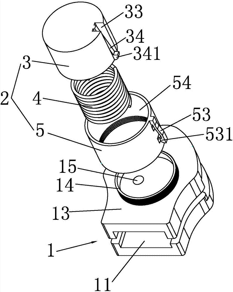
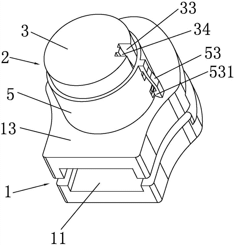
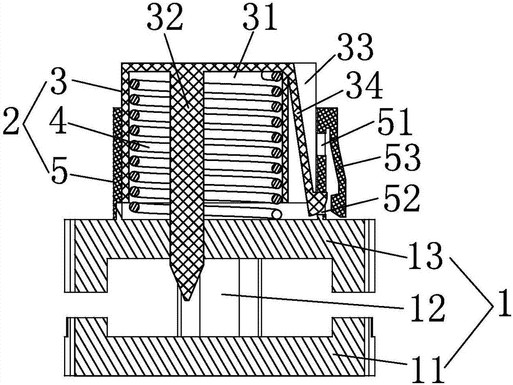
[0017] like Figure 1 to Figure 4 As shown, a push-type self-locking slider includes a slider body 1. The slider body 1 is composed of a lower wing plate 11, a guide post 12 and an upper wing plate 13 that are integrally connected. The top of the upper wing plate 13 is provided with an upwardly convex The bottom of the connecting ring 14 is integrally connected with the top of the upper wing plate 13, the inner part of the connecting ring 14 is provided with a self-locking hole 15 penetrating the upper wing plate 13, and the outer wall of the connecting ring 14 is provided with external threads to connect The top of the ring 14 is provided with a push-type self-locking mechanism 2 , which consists of a movable button 3 , a return spring 4 and a fixed seat 5 . The push-type self-locking mechanism 2 can realize the self-locking or unlocking o...


PUM


Abstract

The invention discloses a pressing-type self-locking pull head, which comprises a pull head main body, wherein the pull head main body is formed by integrally connecting a lower wing plate, a guide pillar and an upper wing plate; a connecting ring is arranged at the top of the upper wing plate; a self-locking hole is formed in the connecting ring; a pressing-type self-locking mechanism is arranged at the top of the connecting ring; the pressing-type self-locking mechanism is composed of a movable button, a reset spring and a fixed seat; an accommodating cavity is formed in the movable button; a self-locking ejector is arranged in the accommodating cavity; an accommodating groove is formed in the outer sidewall of the movable button, and an elastic clamping block is arranged in the accommodating groove; a mounting through hole is formed in the fixed seat; a first clamping groove, a second clamping groove and an elastic oscillating bar are arranged on the sidewall of the fixed seat; the bottom of the fixed seat is fixedly connected to the connecting ring; the movable button is arranged in the fixed seat; the reset spring is arranged in the accommodating cavity; the bottom of the self-locking ejector freely runs through the self-locking hole; and the bottom of the elastic clamping block is clamped in the first clamping groove. The pressing-type self-locking pull head provided by the invention is simple in structure, convenient to assemble and use and good in self-locking effect.

Description

technical field [0001] The invention relates to a slider, in particular to a push-type self-locking slider. Background technique [0002] At present, the self-locking function of the existing self-locking sliders on the market often relies on the horse hook and shrapnel installed on the slider body to realize the self-locking of the slider; the top of the horse hook is subjected to the pressure of the shrapnel, making the The free end of the horse hook catches the zipper teeth to realize the self-locking of the slider; the pull tab on the self-locking slider is pulled, and under the pulling force of the pull tab, the free end of the horse hook is separated from the zipper teeth to realize the unlocking of the slider. , the self-locking slider can be moved. After the movement is completed, the pull-tab is released, and the self-locking slider is restored to self-locking. This self-locking slider that relies on the cooperation of the horse hook and the shrapnel has the follow...

Claims


Application Information

Patent Timeline
IPC IPC(8): A44B19/30
CPCA44B19/303
Inventor 王志杰许婷朱松峰张田
Owner FUJIAN SBS ZIPPER SCI & TECH CO LTD
Why Eureka
Try Eureka