
Control method of spiral CT scanning

A control method and spiral technology, applied in the field of medical imaging systems, can solve the problems of difficulty in guaranteeing and the dose utilization rate will not be significantly improved.

Active Publication Date: 2017-09-15
SHANGHAI UNITED IMAGING HEALTHCARE
View PDF10 Cites 2 Cited by
  • Summary
  • Abstract
  • Description
  • Claims
  • Application Information

AI Technical Summary

Problems solved by technology

In this way, there will be a kind of contradiction. If the error tolerance reserved in advance is small, it is difficult to ensure that it is within the error range during actual execution. There will be no significant increase in utilization

Method used


Image

  • Control method of spiral CT scanning
  • Control method of spiral CT scanning
  • Control method of spiral CT scanning

Examples


Embodiment Construction

[0022] In order to make the above objects, features and advantages of the present invention more obvious and comprehensible, specific implementations of the present invention will be described in detail below in conjunction with the accompanying drawings and embodiments.

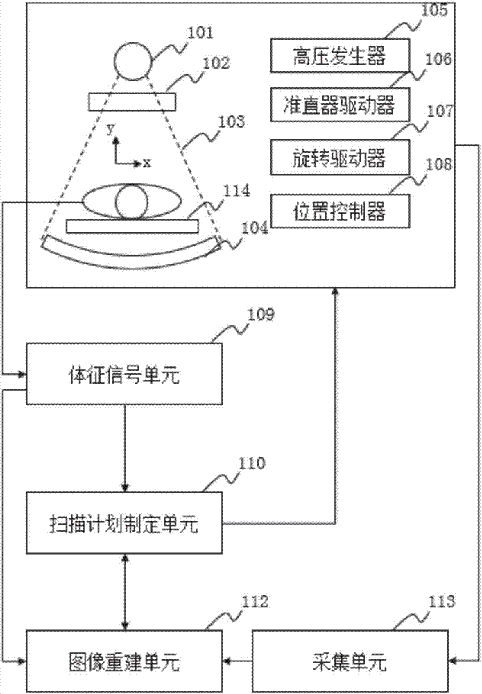
[0023] For a complete understanding of the invention, please refer to figure 1 , showing a schematic structural diagram of a helical CT system in a preferred embodiment of the present invention. The CT system includes but not limited to a CT tube 101, a collimator 102, a detector 104, a high voltage generator 105, a collimator driver 106, a rotary driver 107, a position controller 108, a sign signal unit 109, and a scan planning unit 110 , an image reconstruction unit 112 , an acquisition unit 113 and a scanning bed 114 .

[0024] The high voltage generator 105 is used to receive commands from the scan planning unit 110 and control the work of the CT tube 101 . The CT tube 101 is used to provide X-rays 103...


PUM


Abstract

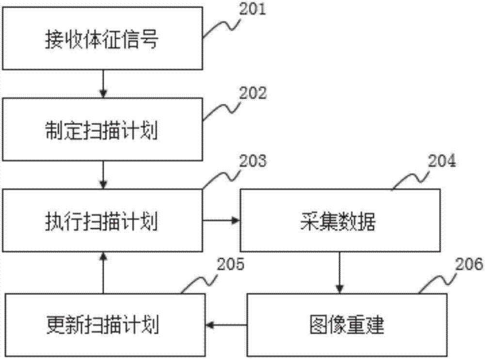
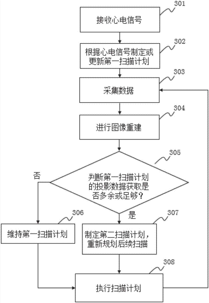
The invention provides a control method of spiral CT equipment. The spiral CT equipment comprises a rotary stand, a CT bulb tube, a detector and a collimator which are fixedly arranged on the rotary stand, and a scanning bed for supporting a scanned object. The method comprises the following steps: receiving sign data of the scanned object; making a first scanning plan in accordance with the sign data; conducting CT scanning on the scanned object in accordance with the first scanning plan so as to acquire first projection data; implementing examination by virtue of the first projection data in accordance with an image reconstruction examination rule; assessing a result of examination in accordance with special conditions, keeping the first scanning plan when an assessment result satisfies a special condition, otherwise generating a second scanning plan and continuing to conduct CT scanning on the scanned object in accordance with the second scanning plan when the assessment result fails to satisfy the special condition, and acquiring second projection data; and implementing image reconstruction in accordance with the first projection data and / or the second projection data.

Description

technical field [0001] The invention relates to a medical imaging system, in particular to a control method for spiral CT scanning. Background technique [0002] Variable-pitch helical CT scanning is a major breakthrough in X-ray imaging technology. It can adjust the pitch at any time according to specific conditions to obtain the best image reconstruction quality. In the diagnosis of medical lesions, according to the needs of diagnosis, when selecting different slice thicknesses for helical scanning, select the appropriate pitch and reconstruction interval to obtain better image quality. For example, when scanning the whole body of a patient, a large pitch can be used for normal parts and a small pitch for lesion parts, which can shorten the scanning time and reduce the radiation dose. At the same time, the variable-pitch helical scanning combined with ECG gating, ECG triggering, respiratory gating and other technologies can effectively reduce artifacts. [0003] The prob...

Claims


Application Information

Patent Timeline
Patent Type & Authority Applications(China)
IPC IPC(8): A61B6/03
CPCA61B6/027A61B6/032A61B6/40A61B6/4208A61B6/5211A61B6/54
Inventor 周家稳
Owner SHANGHAI UNITED IMAGING HEALTHCARE
Learn More