Tooth articulation control machine head guide plate and a production method thereof

A manufacturing method and a technology of the machine head, applied in the fields of dentistry, dental implants, dental prostheses, etc., can solve the problems of increased patient pain, implant failure, implant angle deviation, etc., to reduce the deviation of drilling accuracy and improve positioning accuracy , the effect of reducing loss

Inactive Publication Date: 2017-09-15
SHENZHEN AHEAD FIT TECH CO LTD
View PDF6 Cites 10 Cited by
  • Summary
  • Abstract
  • Description
  • Claims
  • Application Information

AI Technical Summary

Problems solved by technology

Not only increases the pain of the patient, but also may cause bone burns and lead to implant failure
[0005] 2. Accuracy problem. The technical core of the traditional guide plate is actually to prepare the hole by controlling the drill bit through the guide hole. The accuracy of the hole preparation depends on the position of the guide plate, the height of the guide hole, and the position of the hand plate, guide hole and drill bit. Cooperation
The height of most metal sleeves is 5mm. In order not to affect the drilling of the drill bit, the diameter is 0.2mm larger than the matching reamer drill, which will cause a certain angular deviation of the implant.
The hand pressing plate is held by the doctor, and a little carelessness will lead to deviation, reducing the accuracy of the implant hole preparation

Method used


Image

  • Tooth articulation control machine head guide plate and a production method thereof
  • Tooth articulation control machine head guide plate and a production method thereof
  • Tooth articulation control machine head guide plate and a production method thereof

Examples


Embodiment Construction

[0037] In order to make the purpose, technical solutions and advantages of the invention clearer, the technical solutions in the embodiments of the present invention will be clearly and completely described below in conjunction with the accompanying drawings in the embodiments of the present invention. Obviously, the described embodiments are part of the invention Examples, but all of them. Based on the embodiments of the present invention, all other embodiments obtained by persons of ordinary skill in the art without making creative efforts belong to the protection scope of the present invention.

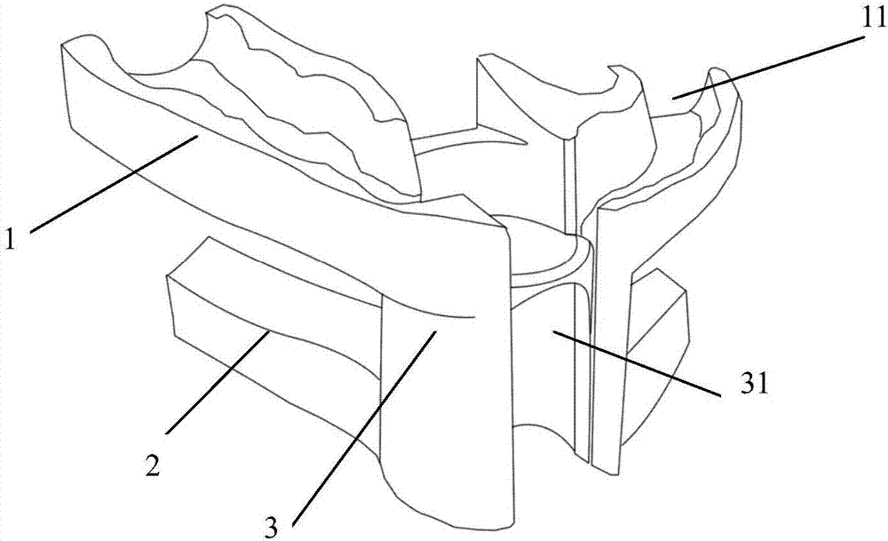
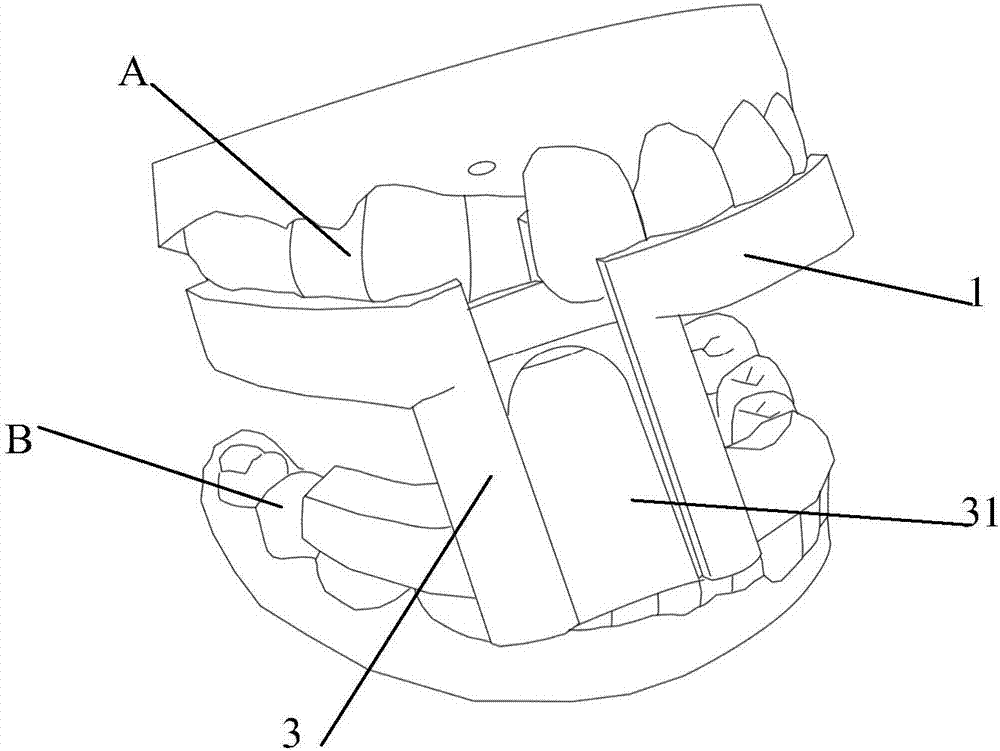
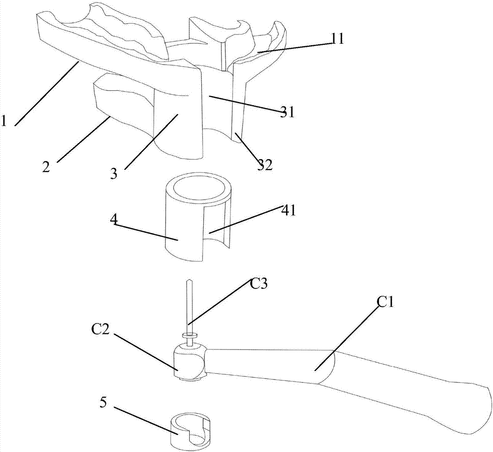
[0038] Such as Figure 1-Figure 5 As shown, the present invention provides an embodiment of the guide plate of the bite control machine head.

[0039] The bite control handpiece guide plate includes: an upper base 1 controlled by upper teeth A, upper alveolar bone or mucous membrane, and a lower base 2 controlled by lower teeth B, lower alveolar bone or mucous membrane. A support...


PUM


Abstract

The present invention discloses a tooth articulation control machine head guide plate and a production method thereof. The guide plate comprises an upper base body controlled by superior teeth, upper alveolar bone or mucous membrane and a lower base body controlled by inferior teeth, lower alveolar bone or mucous membrane, wherein a supporting body is arranged between the upper base body and the lower base body, and a control mechanism for positioning and guiding an implantation machine head on the supporting body, the upper base body or the lower base body. During the use, the guide plate is placed between the superior teeth and the inferior teeth of a patient, and is subjected to articulation fixation respectively with the upper base body and the lower base body through the superior teeth and the inferior teeth, the machine head is placed the control mechanism arranged according to the implantation data, the machine head moves to the alveolar bone along the control mechanism direction during the implantation drilling, and the guide plate performs guiding positioning on the machine head, such that the positioning guiding precision is improved, the direct contact between the guide and the high-speed rotating drill bit is avoided, and the heat generation of the drill bit cannot be additionally increased; and the guide plate can be fixed only through the articulation action of the patient, such that the multi-person operation is not required during the tooth implantation operation, and the tooth implantation difficulty is reduced.

Description

technical field [0001] The invention relates to the technical field of dental implants, in particular to a dental bite control head guide plate and a manufacturing method. Background technique [0002] Dental implant surgery can provide an important restorative option for patients with missing teeth. When implanting, an implant guide is needed to help doctors find the position, depth and direction of the implant more accurately during implant surgery. Combined with modern digital technology, it can reduce operation time and patient pain, and improve the accuracy of seed value and implant value surgery. convenience. [0003] At present, the planting guide plate is composed of a substrate, one or more guide holes, metal collars in the guide holes, hand pressing plates and positioning nails adapted to different drill bits. The positioning of the guide plate is controlled by hand pressing plates matched with drills of different sizes according to the same guide hole on it to r...

Claims


Application Information

Patent Timeline
Patent Type & Authority Applications(China)
IPC IPC(8): A61C8/00
CPCA61C8/0089A61C8/009A61C1/084A61B17/176A61C9/0046A61B34/10A61B2034/105A61B2034/104
Inventor 伍胜富伍美彦
Owner SHENZHEN AHEAD FIT TECH CO LTD
Why Eureka
Try Eureka