Water bath dedustor

A dust collector and water bath technology, applied in fixed filter element filters, gravity filters, chemical instruments and methods, etc., can solve the problems of mixing, reducing the working efficiency of dust collectors, time-consuming and laborious, etc.

Pending Publication Date: 2017-09-15
浙江万源环保机械科技有限公司
View PDF7 Cites 4 Cited by
  • Summary
  • Abstract
  • Description
  • Claims
  • Application Information

AI Technical Summary

Problems solved by technology

Dust collectors are commonly used facilities in boilers and industrial production. Water-bath dust collectors are one of the dust collectors. The existing water-bath dust collectors connect the intake pipe with the water storage cylinder, and the air with dust in the intake pipe Bubbles are formed after entering the water in the water storage tank, the dust in the gas is mixed in the water, and the clean air is discharged from the water surface, but because the air inlet pipe is thicker, the water bubbles formed at the outlet end of the air inlet pipe are larger, and the larger air bubbles are still mixed There is a lot of dust. When the air bubbles surface and burst, the dust inside will still be discharged into the air, resulting in poor dust removal effect of the dust collector. In addition, when a large amount of dust is mixed with water, it will form silt accumulation. In the water storage tank, when the silt accumulates to a certain extent, it is necessary to manually clean the silt in the water storage tank, which is time-consuming and laborious, and the cleaning of the silt is not clean enough, which reduces the working efficiency of the dust collector

Method used


Image

  • Water bath dedustor
  • Water bath dedustor

Examples


Embodiment Construction

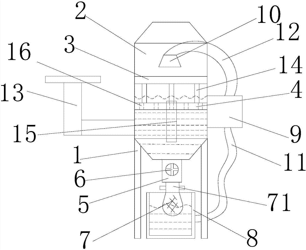
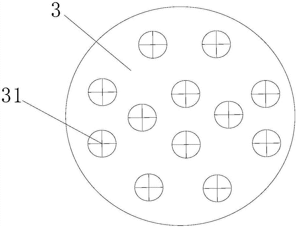
[0014] refer to figure 1 and 2 , a water-bath dust collector of the present invention, comprising a bracket 1, a water storage cylinder 2, a filter screen 3, a floating plate 4, an outlet pipe 5, a valve 6, a filter bag 7, a water tank 8, a water pump 9, a nozzle 10, a suction pipe 11, Water injection pipe 12, air intake pipe 13, support rod 14, observation window 15 and through hole 16, the top of described support 1 is fixedly provided with water storage cylinder 2, and the inner side of described water storage cylinder 2 slides and is provided with the filter screen 3 that horizontally arranges, The bottom of the filter screen 3 is provided with a floating plate 4 slidingly matched with the inner wall of the water storage cylinder 2, the lower part of the water storage cylinder 2 is connected with a water outlet pipe 5, and the side of the water outlet pipe 5 is provided with a valve 6. The outlet end of the water outlet pipe 5 is detachably connected with a first filter b...


PUM


Abstract

The invention discloses a water bath dedustor which comprises a bracket, a water storage barrel, a filter screen, a floating board, a water outlet pipe, a valve, a filter bag, a water tank, a water pump, a nozzle, a water suction pipe, a water injection pipe, a gas inlet pipe, a supporting rod, an observation window and a through hole. The water storage barrel is fixed on the upper portion of the bracket, the filter screen which is horizontally arranged is slidably arranged on the inner side of the water storage barrel, the floating board slidably matched with the inner wall of the water storage barrel is arranged below the filter screen, the lower portion of the water storage barrel is communicated with the water outlet pipe, the valve is arranged on the side portion of the water outlet pipe, the outlet end of the water outlet pipe is detachably connected to the first filter bag, the water tank is arranged right below the first filter bag, the water pump is fixed arranged on the right side portion of the water storage barrel, and the nozzle is arranged right above the filter screen. Compared with the prior art, the efficiency and effect of dedusting can be promoted, sludge is conveniently cleaned, the labor intensity of workers is reduced, water can be recycled, and the water resource is saved.

Description

【Technical field】 [0001] The invention relates to the technical field of dust collectors, in particular to a water-bath dust collector. 【Background technique】 [0002] Dust collector is a device that separates dust from flue gas, called dust collector or dust removal equipment. The performance of the dust collector is expressed by the amount of gas that can be handled, the resistance loss when the gas passes through the dust collector, and the dust removal efficiency. At the same time, the price, operation and maintenance costs, service life and difficulty of operation and management of the dust collector are also important factors to consider its performance. Dust collectors are commonly used facilities in boilers and industrial production. Water-bath dust collectors are one of the dust collectors. The existing water-bath dust collectors connect the intake pipe with the water storage cylinder, and the air with dust in the intake pipe Bubbles are formed after entering the ...

Claims


Application Information

Patent Timeline
IPC IPC(8): B01D47/02B01D29/27
CPCB01D29/27B01D47/021B01D47/028Y02A50/2351
Inventor 汤炳
Owner 浙江万源环保机械科技有限公司
Why Eureka
Try Eureka