Base plate cleaning equipment

A technology for cleaning equipment and substrates, applied in the field of display process, can solve problems such as scratching the substrate, and achieve the effect of improving product yield and product quality

Inactive Publication Date: 2017-09-15
SHENZHEN CHINA STAR OPTOELECTRONICS TECH CO LTD
View PDF7 Cites 5 Cited by
  • Summary
  • Abstract
  • Description
  • Claims
  • Application Information

AI Technical Summary

Problems solved by technology

like figure 1 As shown, an existing substrate cleaning equipment includes: a load bar 100, a brush 300 arranged on the outer surface of the load bar 100, a drive device 200 connected to one end of the load bar 100, and a drive device 200 connected to one end of the load bar 100. The rod 100 is fixed on the bearing 400 on the wet process machine. When cleaning the substrate, the cleaning liquid is provided to the surface of the substrate, and the driving device 200 drives the bearing rod 100 and the brush 300 on it to rotate and clean the surface of the substrate. During the production process, due to the uneven flushing of the cleaning liquid on the brush 300, some particles will be hidden in the brush 300 for a long time, and then the brush 300 will bring the particles to the substrate when cleaning the substrate, and even scrape the substrate. damage substrate

Method used


Image

  • Base plate cleaning equipment
  • Base plate cleaning equipment
  • Base plate cleaning equipment

Examples


Embodiment Construction

[0028] In order to further illustrate the technical means adopted by the present invention and its effects, the following describes in detail in conjunction with preferred embodiments of the present invention and accompanying drawings.

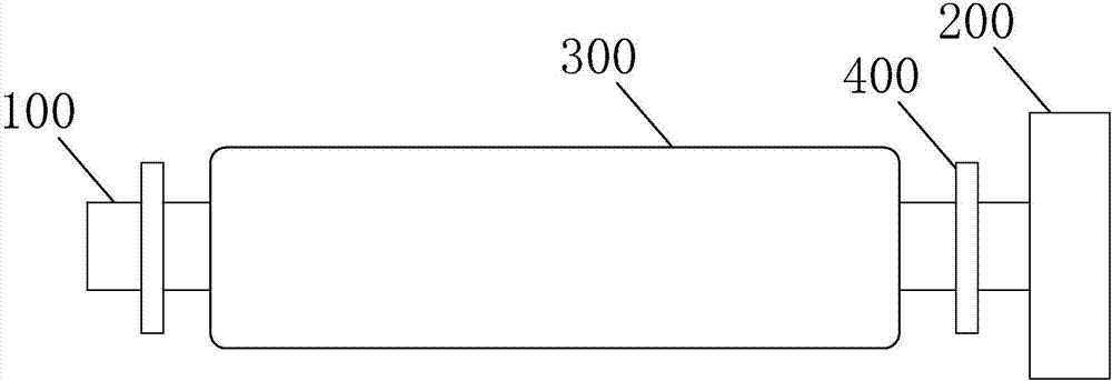
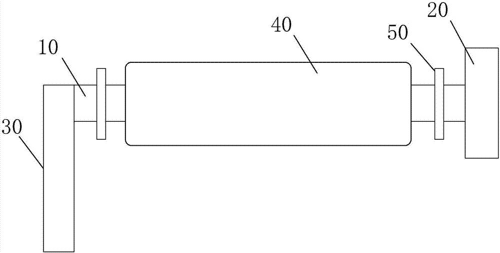
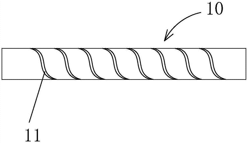
[0029] see figure 2 , the present invention provides a substrate cleaning device, comprising: a hollow bearing rod 10, a brush 40 arranged on the outer surface of the bearing rod 10, a driving device 20 connected to one end of the bearing rod 10, and a rotating device connected to the other end of the bearing rod 10 Connected inlet tube 30; see image 3 or Figure 4 , the carrying rod 10 is provided with a plurality of water outlets 11;

[0030] The liquid inlet pipe 30 is used to pass cleaning liquid into the carrying rod 10;

[0031] The water outlet 11 is used to spray the cleaning liquid in the bearing rod 10 from the inside of the bearing rod 10 to the outside of the bearing rod 10 , so as to wet and clean the brush 40 .

[0032] It ...


PUM


Abstract

The invention provides base plate cleaning equipment. The base plate cleaning equipment comprises a hollow bearing rod, a brush arranged on the outer surface of the bearing rod, a driving device connected with one end of the bearing rod, and a liquid inlet pipe rotationally connected with the other end of the bearing rod. A plurality of water outlets are formed in the bearing rod. Cleaning liquid is led into the bearing rod through the liquid inlet pipe. The cleaning liquid in the bearing rod is sprayed out from the multiple water outlets to the exterior of the bearing rod, so that the brush is wetted evenly and can be effectively cleaned, remaining particles in the brush are removed, the problem that during base plate cleaning, the particles in the brush are brought to the base plate and scratch the base plate is avoided, and the product yield rate and quality are improved.

Description

technical field [0001] The invention relates to the field of display manufacturing process, in particular to a substrate cleaning device. Background technique [0002] With the development of display technology, liquid crystal displays (Liquid Crystal Display, LCD) and other flat display devices are widely used in mobile phones, televisions, personal Various consumer electronic products such as digital assistants, digital cameras, notebook computers, and desktop computers have become the mainstream of display devices. [0003] Usually, the liquid crystal display panel consists of a color filter substrate (Color Filter, CF), a thin film transistor substrate (Thin Film Transistor, TFT), a liquid crystal (LC, Liquid Crystal) sandwiched between the color filter substrate and the thin film transistor substrate, and a sealant frame (Sealant ), the molding process generally includes: the front-end array (Array) process (film, yellow light, etching and stripping), the middle-stage ...

Claims


Application Information

Patent Timeline
Patent Type & Authority Applications(China)
IPC IPC(8): B08B1/04H01L21/67
CPCB08B1/002B08B1/007B08B1/04H01L21/67046
Inventor 李嘉
Owner SHENZHEN CHINA STAR OPTOELECTRONICS TECH CO LTD
Why Eureka
Try Eureka