An electro-pneumatic braking system and mitigation method for railway passenger cars

A technology of electro-pneumatic braking and railway passenger cars, which is applied in the direction of railway car body parts, brakes, pneumatic brakes, etc., which can solve problems such as installation and maintenance inconvenience, increased compressed air consumption, and fewer stages of relief times, etc., to improve products Reliability and work efficiency, flexible maneuverability of braking force, effect of reducing operation cost

Active Publication Date: 2019-06-14
CRRC QINGDAO SIFANG ROLLING STOCK RES INST +1
View PDF6 Cites 0 Cited by
  • Summary
  • Abstract
  • Description
  • Claims
  • Application Information

AI Technical Summary

Problems solved by technology

[0003] Although the air brakes of some existing passenger cars have the function of stage release, because the pressure change of the train pipe is controlled by the locomotive brake and transmitted from front to back, the stage relief cannot be synchronized, and the number of stage relief is small, which affects the flexible operation of the braking force Most passenger car air brakes do not have a stage relief function, and can only achieve one-time relief. Once the locomotive brake controls the train tube boost, the compressed air in each passenger car brake cylinder will be emptied, and the brake cylinder will be released when braking again. The pressure rises from 0, increasing the consumption of compressed air
The existing electro-pneumatic braking device for passenger cars is affected by the volume of the working air cylinder and its air pressure to participate in the pressure control. The working air cylinder is inflated to the train pipe by releasing the electromagnetic valve, so synchronous relief cannot be achieved, and the number of relief is limited.
In addition, the existing sensors installed on some passenger cars for monitoring the pressure of the brake system are installed scatteredly on each air pipeline, the air circuit connection is relatively complicated, and there are many potential leakage points. Each has a protective cover, and the protection is more troublesome. There are many inconveniences in installation and maintenance

Method used


Image

  • An electro-pneumatic braking system and mitigation method for railway passenger cars
  • An electro-pneumatic braking system and mitigation method for railway passenger cars
  • An electro-pneumatic braking system and mitigation method for railway passenger cars

Examples


Embodiment Construction

[0029] The application will be further described in detail below in conjunction with the accompanying drawings and embodiments. It should be understood that the specific embodiments described here are only used to explain related inventions, not to limit the invention. It should also be noted that, for ease of description, only parts related to the invention are shown in the drawings.

[0030] It should be noted that, in the case of no conflict, the embodiments in the present application and the features in the embodiments can be combined with each other. The present application will be described in detail below with reference to the accompanying drawings and embodiments.

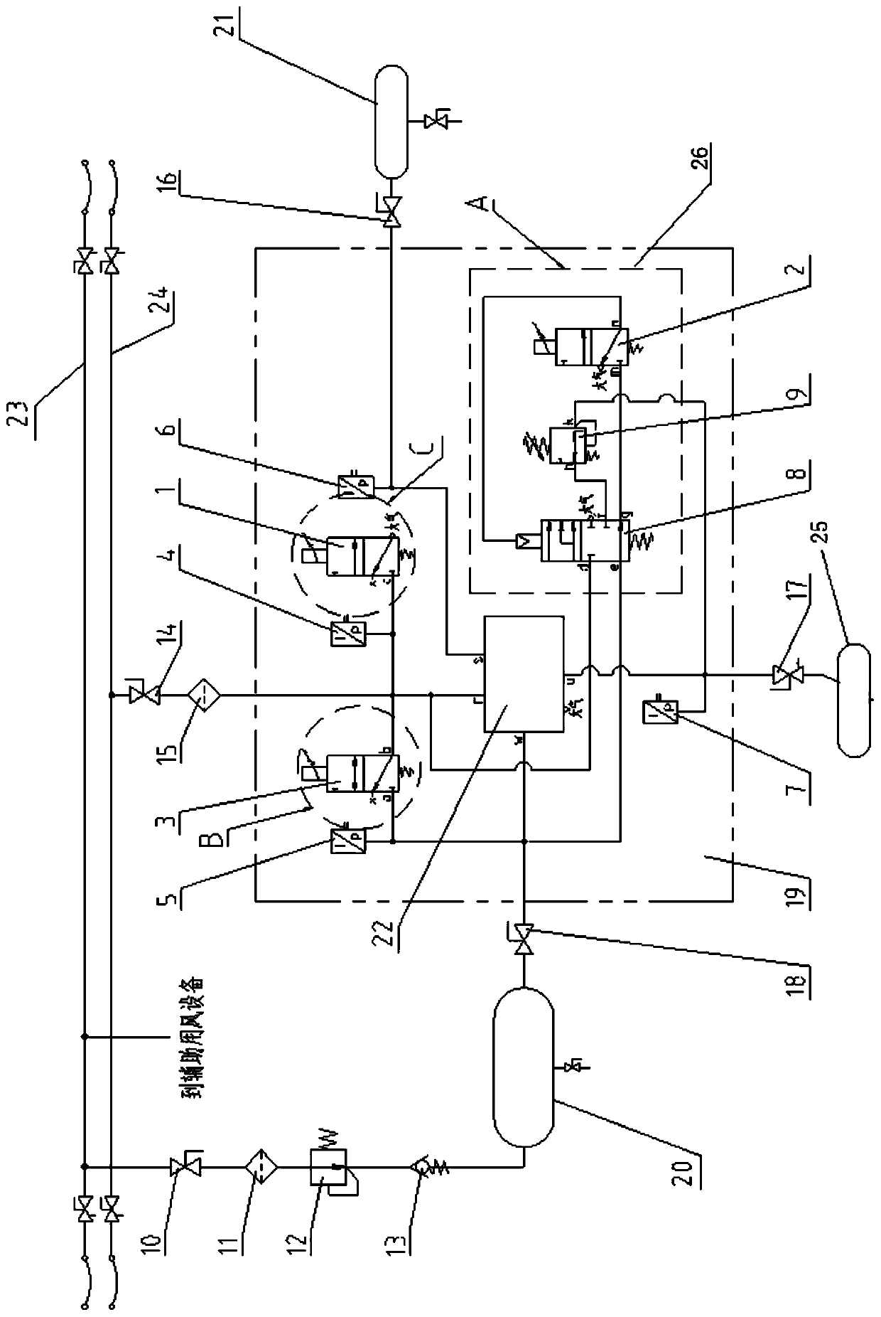
[0031] Please refer to figure 1 , a principle diagram of the air circuit of the electro-pneumatic brake system of a railway passenger car, mainly including a main air pipe 23, a train pipe 24, a relief solenoid valve 3, an auxiliary air cylinder 20, and a distribution valve 22, and the distribution valve ...


PUM


Abstract

The invention relates to the technical field of rail transportation equipment, in particular to an electro-pneumatic braking system and mitigation method for a railway passenger train. The electro-pneumatic braking system comprises a main air tube, a train tube, a mitigation magnetic valve, a service braking magnetic valve, an emergency electro-pneumatic device, an auxiliary air cylinder and a distribution valve. The distribution valve communicates with the train tube through a gas path and a gas path unit. One end of the auxiliary air cylinder communicates with the train tube through the distribution valve, and preferably, the other end of the auxiliary air cylinder communicates with the main air tube through a gas path and a gas path unit. The auxiliary air cylinder can be filled with compressed air by the main air tube. The mitigation magnetic valve is installed on the gas path between the auxiliary air cylinder and the train tube so that during mitigation after the braking, by the controlling of the mitigation magnetic valve, the train tube can be constantly filled with the compressed air by the auxiliary air cylinder, the synchronization of the phase mitigation function is ensured, and the frequency of the phase mitigation is increased; and the riding comfort is improved for passengers, the maneuverability of the braking force is more flexible, the consumption of the compressed air can be reduced, and the energy conservation function is achieved.

Description

technical field [0001] The invention belongs to the technical field of rail transit equipment, and in particular relates to an electropneumatic braking system and a mitigation method for a railway passenger car. Background technique [0002] my country's main railway passenger trains are composed of locomotives (head cars) and passenger cars. Both locomotives and passenger cars use automatic air brakes. The air brakes control the change of compressed air pressure in the train pipe to control the generation of passenger car brakes. The power thus controls the speed of the train. Specifically, the exhaust and decompression of the train tube generates braking force, inflation boosts the pressure relief (relieving refers to reducing the braking force or reducing the braking force to 0), and the train tube transmits the brake and release commands through pressure changes. At the same time, it is also responsible for supplying compressed air to the passenger car brake. Since the ...

Claims


Application Information

Patent Timeline
Patent Type & Authority Patents(China)
IPC IPC(8): B60T13/66B60T13/36B61H11/06
CPCB60T13/365B60T13/665B61H11/06
Inventor 李培署王风洲于钦顺刘晓京鲁文超
Owner CRRC QINGDAO SIFANG ROLLING STOCK RES INST
Why Eureka
Try Eureka