Ground charging and conveying system of vehicle-mounted integrated soil remediation device

A soil remediation and conveying system technology, which is applied to conveyors, conveyor objects, transportation and packaging, etc., can solve problems such as affecting remediation efficiency and inability to load multiple sets of remediation devices, and achieves easy maintenance and replacement, simple structure, and improved performance. effect of speed

Pending Publication Date: 2017-09-15
程刚
8 Cites 1 Cited by

AI-Extracted Technical Summary

Problems solved by technology

[0004] The existing ground feeding and conveying devices are basically fixedly installed with the equipment to work on specific occasions, and most of them use ...

Abstract

The invention discloses a ground charging and conveying system of a vehicle-mounted integrated soil remediation device. The ground charging and conveying system comprises a feeding device and belt conveying systems; the feeding device comprises a vibratory feeder, a crusher and a separatory funnel; the separatory funnel is located below the vibratory feeder; the crusher is located in front of the vibratory feeder; an outlet of the vibratory feeder and an outlet of the crusher are connected with the separatory funnel; a plurality of outlets are formed in the lower part of the separatory funnel; each outlet corresponds to one belt conveying system; and an outlet of each belt conveying system corresponds to one soil remediation device. With the adoption of the ground charging and conveying system, the multiple soil remediation devices can be placed together to work, thus the speed of soil remediation is raised substantially. To-be-treated soil is pretreated in a conveying stage before the treatment on the to-be-treated soil, thus the equipment utilization ratio is raised substantially. The to-be-treated soil is subjected to centralized pretreatment, and the one-to-many device function is realized. Various parts in ground charging and conveying system are standard parts, thus the maintenance and replacement are facilitated.

Application Domain

ConveyorsRollers

Technology Topic

EngineeringSoil remediation +4

Image

  • Ground charging and conveying system of vehicle-mounted integrated soil remediation device
  • Ground charging and conveying system of vehicle-mounted integrated soil remediation device

Examples

  • Experimental program(1)

Example Embodiment

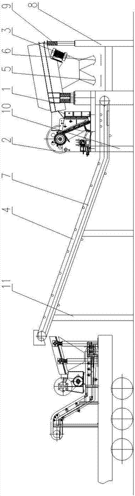
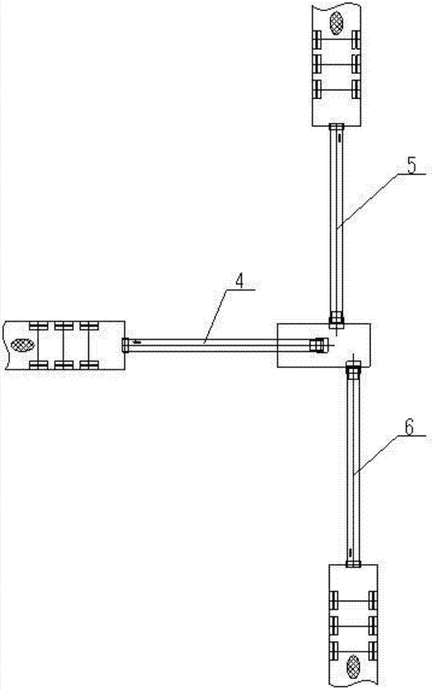
[0022] The present invention will be further described below in conjunction with the accompanying drawings. like Figure 1-2 Shown, a kind of vehicle-mounted integrated soil remediation device ground feeding conveying system comprises a feeding device and a belt conveying system; the described feeding device includes a vibrating feeder 1, a crusher 2 and a distribution funnel 3; the The vibrating feeder 1 is installed on the ground through the feeder bracket 8; the distributing funnel 3 is located below the vibrating feeder 1; the crusher 2 is located in front of the vibrating feeder 1. The machine support 10 is installed on the ground; the outlets of the vibrating feeder 1 and the crusher 2 are connected to the distribution funnel 3; there are multiple outlets below the distribution funnel 3, and each outlet corresponds to a set of belts Conveying system, the outlet of each belt conveying system corresponds to a set of soil remediation device.
[0023] Further, a damping spring 9 is arranged between the vibrating feeder 1 and the feeder support 8 .
[0024] Further, the belt conveying system includes a belt, a belt frame 7 and a belt installation bracket 11, the belt frame 7 is an integral structure, composed of an inclined section and a horizontal section, and the horizontal section is arranged on the side of the material distribution funnel 3 Below; the belt frame 7 is fixed on the belt mounting bracket 11, and the lower end of the belt mounting bracket 11 is fixed on the ground; the upper and lower sides of the belt frame 7 are evenly equipped with a plurality of rollers, and the throwing head An electric drum is installed, and a reversing roller is installed at the material receiving end, and the belt is looped around the electric drum, the reversing roller and each supporting roller.
[0025] Further, there are three sets of belt conveying systems, namely No. 1 belt conveying system 4, No. 2 belt conveying system 5 and No. 3 belt conveying system 6, and the three sets of belt conveying systems are arranged radially.
[0026] Further, the inclination angle between the inclined section of the belt conveyor system and the horizontal plane is 20-30 degrees.
[0027] Further, the belt conveying system further includes a buffer idler, and the electric drum, the diverting pulley, the upper idler, the lower idler and the buffer idler are all mounted on the frame through bolt groups.
[0028] Further, the electric drum is directly connected to the motor through a built-in speed reducer.
[0029] Working method of the present invention is as follows:
[0030] A. The soil is transported to the vibrating feeder 1 by the ground excavator;
[0031] B. The vibrating feeder 1 transports the qualified soil clods to the distribution funnel 3; the larger soil clods are first sent to the crusher 2, and then sent to the distribution funnel 3 after crushing.
[0032] C. The material distribution funnel 3 collects the soil to be treated, and evenly outputs it to multiple sets of belt conveying systems through multiple outlets.
[0033] D. The belt conveyor system transports the soil to the corresponding soil remediation device.
[0034] Installation method of the present invention is as follows:
[0035] First, install all the auxiliary pulleys and rollers of the belt on the belt frame 7 to form a belt conveying system and load it into the vehicle. After the vehicle arrives at the soil site to be treated, unload the belt installation bracket 11 from the vehicle and install it on the ground On, then the belt conveyor system is installed on the belt installation bracket 11 as a whole. Secondly, the crusher support 10 is installed on the ground, and then the crusher 2 is installed on the crusher support 10 . Finally, the vibrating feeder 1 support is installed on the ground, and the vibrating feeder 1 is installed on the feeder support 8 again.
[0036] The disassembly method of the present invention is as follows: first, the connecting bolts of the vibrating feeder 1 are opened, then the vibrating feeder is disassembled, placed on the car by a crane, and then the feeder bracket 8 is unloaded from the ground, placed in the car. Secondly, the connecting bolts of the crusher 2 are opened, then the crusher 2 is disassembled, placed on the car by a crane, and then the crusher support 10 is unloaded from the ground and placed on the car. Finally, the connecting bolts of the belt conveying system are opened, then the belt conveying system is disassembled, placed on the car by a crane, and then the belt mounting bracket 11 is unloaded from the ground and placed on the car.
[0037] The present invention is not limited to this embodiment, and any equivalent ideas or changes within the technical scope disclosed in the present invention are listed in the protection scope of the present invention.

PUM

no PUM

Description & Claims & Application Information

We can also present the details of the Description, Claims and Application information to help users get a comprehensive understanding of the technical details of the patent, such as background art, summary of invention, brief description of drawings, description of embodiments, and other original content. On the other hand, users can also determine the specific scope of protection of the technology through the list of claims; as well as understand the changes in the life cycle of the technology with the presentation of the patent timeline. Login to view more.

Similar technology patents

Method for measuring particle size distribution of particles, and apparatus thereof

InactiveCN103983546Aacceleratelower requirement
Owner:INST OF HIGH ENERGY PHYSICS CHINESE ACADEMY OF SCI

HBase-based incremental index creation and retrieval method

ActiveCN103390038ACapacity issues raisedaccelerate
Owner:XI AN JIAOTONG UNIV

Method and device for quickly inquiring and calculating MangoDB cluster

InactiveCN103207919Aaccelerate
Owner:BEIJING IZP NETWORK TECH CO LTD

Classification and recommendation of technical efficacy words

  • increase profit
  • accelerate

Hydrodewaxing method for diesel fraction

ActiveCN102453531ARaise the reaction temperatureincrease profit
Owner:CHINA PETROLEUM & CHEM CORP +1

Full-period electric pressure cooker production control method

InactiveCN107713732ATargetedincrease profit
Owner:GUANGDONG HUILIPU ROAD & BRIDGE INFORMATION ENG

Mobile phone

InactiveCN102938796Aincrease profit
Owner:ZTE CORP

Window display method and system of application program and mobile terminal

ActiveCN102999253Aincrease profit
Owner:BEIJING QIYI CENTURY SCI & TECH CO LTD

Three-dimensional circuit manufacturing process and composite components of laser plastic material and manufacturing method

ActiveCN101859613Aaccelerateaccelerated continuous motion
Owner:深圳市微航磁电技术有限公司

Failure recognition method and system based on neural network self-learning

ActiveCN103914735ASpeed ​​up fault identificationaccelerate
Owner:BEIJING TAILEDE INFORMATION TECH

Method and apparatus for loading web pages

ActiveCN101369284Ashorten the timeaccelerate
Owner:BEIJING SOGOU TECHNOLOGY DEVELOPMENT CO LTD
Why Eureka
Try Eureka