
Door-closing buffer assembly

A technology of components and clips, applied in door/window accessories, wing parts, wing closers, etc., can solve the problem that the decoupling device and the buffer component cannot adjust the position of the interaction force by themselves, the installation of the damper is inconvenient, and the impact Issues such as service life and user experience

Active Publication Date: 2017-09-15
肇庆市弘丰智扬精密制品有限公司
View PDF6 Cites 4 Cited by
  • Summary
  • Abstract
  • Description
  • Claims
  • Application Information

AI Technical Summary

Problems solved by technology

[0002] Existing sliding doors will be equipped with dampers to reduce the impact force and noise when closing the door, but the toggles of the existing door closing buffer components are all vertically arranged, and there is no room for buffering when the decoupler and the toggle collide , produce greater impact and noise, and the door will also jump, which will affect the service life and user experience
In addition, the traditional damper is inconvenient to install, and the decoupler and the buffer assembly need to be hooked up in advance. The decoupler and the buffer assembly cannot adjust the position of the interaction force by themselves, and the traditional damper needs to be additionally installed. cost of production

Method used


Image

  • Door-closing buffer assembly
  • Door-closing buffer assembly
  • Door-closing buffer assembly

Examples


Embodiment 1

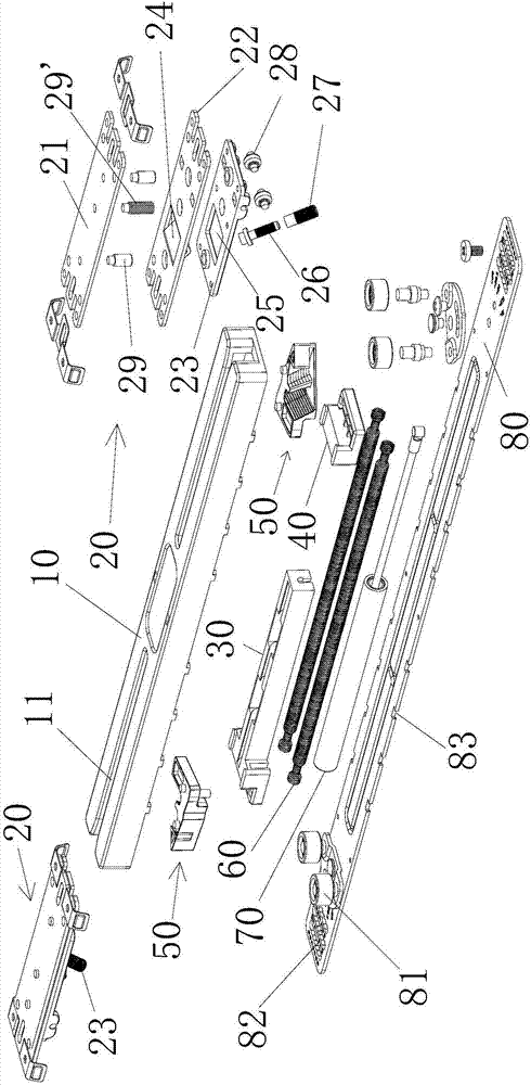
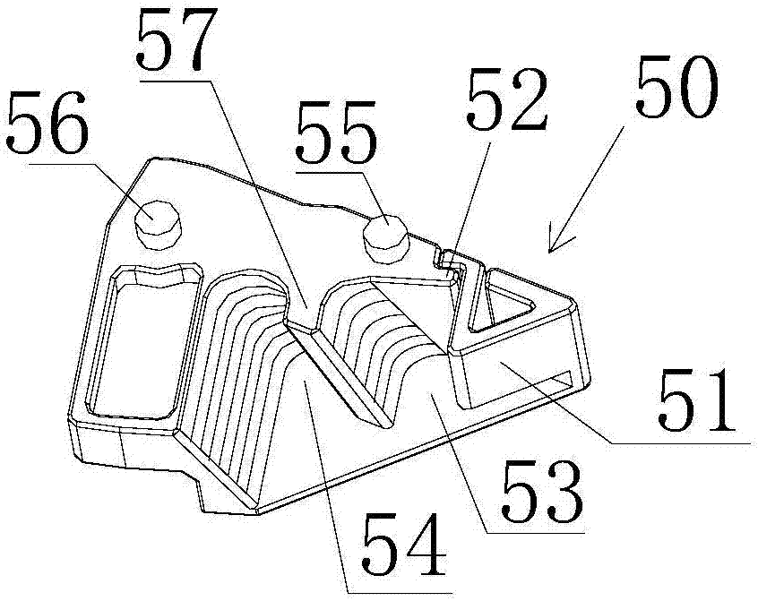
[0024] Such as Figure 1-7 As shown, a door closing buffer assembly of this embodiment includes a housing 10 provided with a groove 11, a limit device 20 provided with a toggle member 26, and a damping device provided in the housing 10. The described The toggle member 26 extends into the housing 10 through the groove 11. The damping device includes a spring 60, a damper 70, a sliding seat 40 and a decoupling device 50. There are two sliding seats 40, respectively connected to the spring 60. It is connected with the two ends of the damper 70, and the decoupling device 50 is also provided with two, and the two sliding seats 40 are rotatably connected with the two decoupling devices 50, and the described decoupling device 50 is provided with a first clip position 53 and The second clamping position 54, the first clamping position 53 is surrounded by the elastic baffle 51 and the protruding part 57 on three sides, and the second clamping position 54 is concaved by the protruding p...

Embodiment 2

[0026] Such as Figure 1-7 As shown, this embodiment has been improved on the basis of Embodiment 1. The decoupling device 50 is also provided with a bullet-resistant component 52, and the elastic component 51 is provided with a hook. After the elastic component 51 rebounds, the hook hooks on the resistance On the spring part 52. Due to the active force of the spring 60, the uncoupling device 50 is closely attached to the sliding seat 40, and the front end of the uncoupling device 50 is arranged in a triangle, and the elastic part 51 is installed on one face of the triangle, and the toggle part 26 hits the elastic part 51, and the elastic part 51 The component 51 bounces open, the toggle piece 26 enters the first clamping position 53, and then the elastic component 51 bounces back to form an accommodation area together with the first clamping position 53, and the bullet-resistant component 52 restricts the rebound of the elastic component 51 itinerary. At this time, no matte...

Embodiment 3

[0028] Such as Figure 1-7 As shown, this embodiment improves the movable installation method of the decoupling device 50 and the sliding seat 40, the sliding seat 40 is provided with a fulcrum hole 41, the decoupling device 50 is provided with a fulcrum column 56, and the fulcrum The column 56 is arranged in the fulcrum hole 41 , and the decoupling device 50 rotates relative to the decoupling device 50 through the fulcrum column 56 , and the sliding seat 40 is also provided with a sliding guide boss 42 . The uncoupling device 50 takes the fulcrum column 56 as a fulcrum and rotates relative to the sliding seat 40 , but due to the effect of the spring 60 , the uncoupling device 50 is closely connected with the sliding seat 40 without being affected by other external forces. The guide boss 42 plays a role in making the sliding seat 40 move directionally.


PUM


Abstract

The invention relates to the technical field of door-closing buffering, in particular to a door-closing buffer assembly. According to the door-closing buffer assembly, a decoupling device is provided with a first clamping piece position and a second clamping piece position, the first clamping piece position is defined by an elastic baffle and three sides of a protrusive component, and the second clamping piece position is formed by the concave portion of the protrusive component; a shifting member moves along a groove opposite to the decoupling device, the decoupling device rotates, and the shifting member is disposed in the first clamping piece position or the second clamping piece position alternatively. According to the door-closing buffer assembly, a door can return after being opened or closed through tensile force provided by a spring, and the collision strength can be adjusted through coordination of a damping device and a limiting device when the door is opened and closed. The door-closing buffer assembly is further provided with the decoupling device, the decoupling device is provided with the first clamping piece position and the second clamping piece position, and the decoupling device can rotate, so that the limiting device is buckled with the first clamping piece position or the second clamping piece position alternatively, and mounting is convenient.

Description

【Technical field】 [0001] The invention relates to the technical field of door closing buffer, in particular to a door closing buffer assembly. 【Background technique】 [0002] Existing sliding doors will be equipped with dampers to reduce the impact force and noise when closing the door, but the toggles of the existing door closing buffer components are all vertically arranged, and there is no room for buffering when the decoupler and the toggle collide , resulting in greater impact and noise, and the door will bounce, affecting the service life and user experience. In addition, the traditional damper is inconvenient to install, and the decoupler and the buffer assembly need to be hooked up in advance. The decoupler and the buffer assembly cannot adjust the position of the interaction force by themselves, and the traditional damper needs to install an additional track of the decoupler to improve production cost. 【Content of invention】 [0003] The present invention aims t...

Claims


Application Information

Patent Timeline
Patent Type & Authority Applications(China)
IPC IPC(8): E05F5/00E05F5/06E05F1/16
CPCE05F1/16E05F5/003E05F5/06E05Y2900/132
Inventor 谭发杨
Owner 肇庆市弘丰智扬精密制品有限公司
Learn More