
Torsional vibration reducing device based on hydraulic damping cam

A technology of hydraulic damping and torsional vibration reduction, applied in the direction of rotation vibration suppression, spring/shock absorber, vibration suppression adjustment, etc., can solve the problems of insufficient transmission stability, poor versatility and reliability, etc. To the effect of flowing quickly and improving the effect

Active Publication Date: 2017-09-15
HANGZHOU DIANZI UNIV
View PDF6 Cites 16 Cited by
  • Summary
  • Abstract
  • Description
  • Claims
  • Application Information

AI Technical Summary

Problems solved by technology

These torsional vibration damping devices can better absorb and damp vibration, but the transmission is not stable enough, and the versatility and reliability are poor.

Method used


Image

  • Torsional vibration reducing device based on hydraulic damping cam
  • Torsional vibration reducing device based on hydraulic damping cam
  • Torsional vibration reducing device based on hydraulic damping cam

Examples


Embodiment Construction

[0033] The present invention will be further elaborated below in conjunction with accompanying drawing:

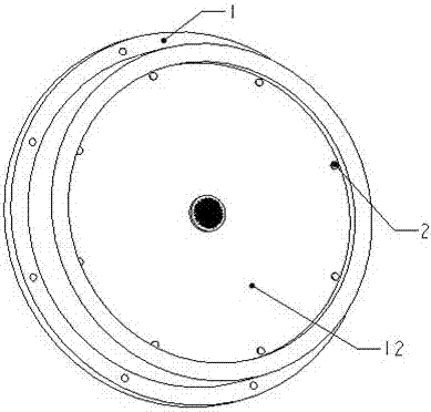
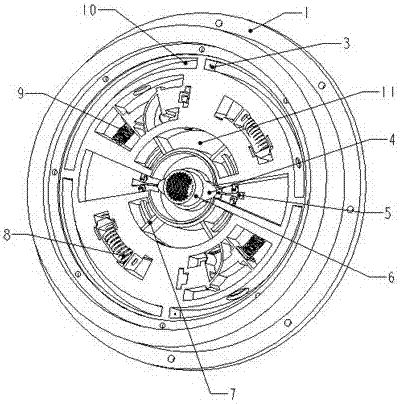
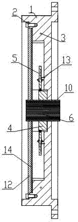
[0034] Such as figure 1 , 2 As shown, the torsional vibration damping device based on the hydraulic damping cam of the present invention mainly includes a flange plate 1, a central cam 4, a cam push rod 5, a spline shaft 6, an arc push rod 7, a direction control window 8, and a decompression window 9. Annular oil tank 10, arc-shaped oil cylinder 11, sealing cover 12.

[0035] The outer edge of the flange 1 is equidistantly provided with a plurality of bolt holes for fixing.

[0036] The sealing cover 12 is screwed to the flange plate through the threaded hole to form a closed space including a decompression window and a direction control window, and the inner cavity of the closed space is filled with oil 15 .

[0037] As shown in FIG. 3 , the outer edge of the flange 1 is provided with a plurality of assembly holes, and the assembly holes are equally spaced.

[0038] T...


PUM


Abstract

The invention discloses a torsional vibration reduction device based on a hydraulic damping cam. The torsional vibration reduction device comprises a flange, a central cam, cam pushing rods, a spline shaft, arc-shaped pushing rods, direction control windows, pressure reduction windows, a ring-shaped oil groove, arc-shaped oil cylinders, a sealing cover and the like, wherein the sealing cover is arranged on one side of the flange; the sealing cover and the flange are connected through screws, and then an enclosed space comprising the pressure reduction windows and the direction control windows is formed; the enclosed space is fully filled with an oil liquid; the spline shaft and the central cam are in interference fit with each other and connected into a whole; the whole of the spline shaft and the central cam is matched and connected with the flange; the spline shaft is connected with a main transmission shaft; the central cam is driven by the main transmission shaft to rotate; through the translation of the cam pushing rods, the arc-shaped pushing rods are driven to rotate in the arc-shaped oil cylinders; the oil liquid is extruded and enters the pressure reduction windows for pressure reduction; the flowing direction of the oil liquid is controlled through the direction control windows; the oil liquid flows in the ring-shaped oil groove on the periphery of the flange; and through further pressure reduction at damping holes, the torsional force is reduced. The torsional vibration reduction device disclosed by the invention has the advantages that the transmission is smooth and steady; the speed is high; the mechanical energy is converted into the hydraulic energy; and the vibration reduction effect is good.

Description

technical field [0001] The invention relates to a torsional vibration damper, in particular to a torsional vibration damping device based on a hydraulic damping cam. Background technique [0002] Torsional vibrations commonly occur in machines that rotate. Torsional vibration is extremely destructive, causing drastic changes in torsional stress, causing severe wear on the rotating shaft, and even causing the drive shaft of the transmission system to break. One of the main sources of vibration and noise in automobile structures is the torsional vibration of the automobile transmission system. The torsional vibration of the car not only affects the comfort and stability of the car, but also plays a decisive role in the economy and safety of the car; the torsional vibration of the main drive system of the rolling mill occurs when the torque is transmitted, which affects the normal operation of the rolling workshop. Production has serious implications. The torsional vibration...

Claims


Application Information

Patent Timeline
Patent Type & Authority Applications(China)
IPC IPC(8): F16F15/16
CPCF16F15/161
Inventor 王桥医朱媛过山张秋波
Owner HANGZHOU DIANZI UNIV
Learn More