
A device and method for measuring the tensile strength of soil using a direct shear instrument

A technology of tensile strength and direct shear instrument, which is applied in the direction of applying stable tension/pressure to test the strength of materials, can solve the problems of smaller cross-section, increase of soil tensile strength, soil compression deformation, etc., to achieve The effect of overcoming the influence of self-weight, convenient operation and simple structure

Active Publication Date: 2020-04-03
HOHAI UNIV
View PDF2 Cites 0 Cited by
  • Summary
  • Abstract
  • Description
  • Claims
  • Application Information

AI Technical Summary

Problems solved by technology

[0004] The main defects of the horizontal uniaxial tensile test devices that are widely used at present are: (1) for regular samples such as rectangles or cylinders, since the samples are provided by the friction between the fixture and the soil, If the clamping force is too small, the sample cannot be effectively clamped; and if the clamping force is too large, the soil at both ends of the sample will be compressed and deformed, so that the cross-section at both ends of the sample will become smaller. The sample is likely to be damaged at the edge of the fixture; (2) For the hourglass-shaped sample, since the sample soil is directly prepared in the hourglass-shaped mold, the middle part of the mold is disconnected, and then applied through the lugs at both ends of the mold. The tension is on the soil. In this way, the mold has a certain restraint effect on the internal soil. This part of the restraint has a certain contribution to the tensile capacity of the soil, which increases the measured tensile strength of the soil in disguise; (3) In the horizontal tensile device, the sample is in direct contact with the test platform, and there is a certain amount of friction. Although slide rails are used between the sample and the platform, it is difficult to ensure that the soil will not be disturbed by the pulley during stretching peeling off

Method used


Image

  • A device and method for measuring the tensile strength of soil using a direct shear instrument
  • A device and method for measuring the tensile strength of soil using a direct shear instrument
  • A device and method for measuring the tensile strength of soil using a direct shear instrument

Examples


Embodiment Construction

[0026] The technical solutions of the present invention will be described in detail below in conjunction with the accompanying drawings and through embodiments.

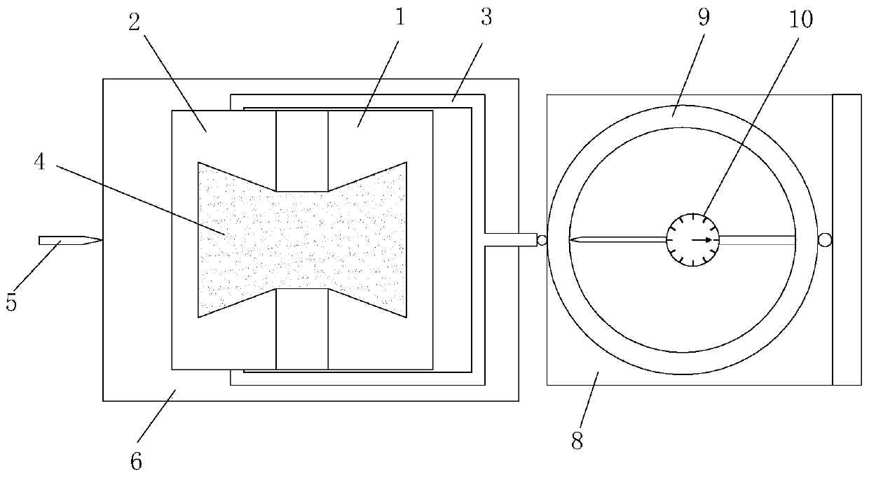
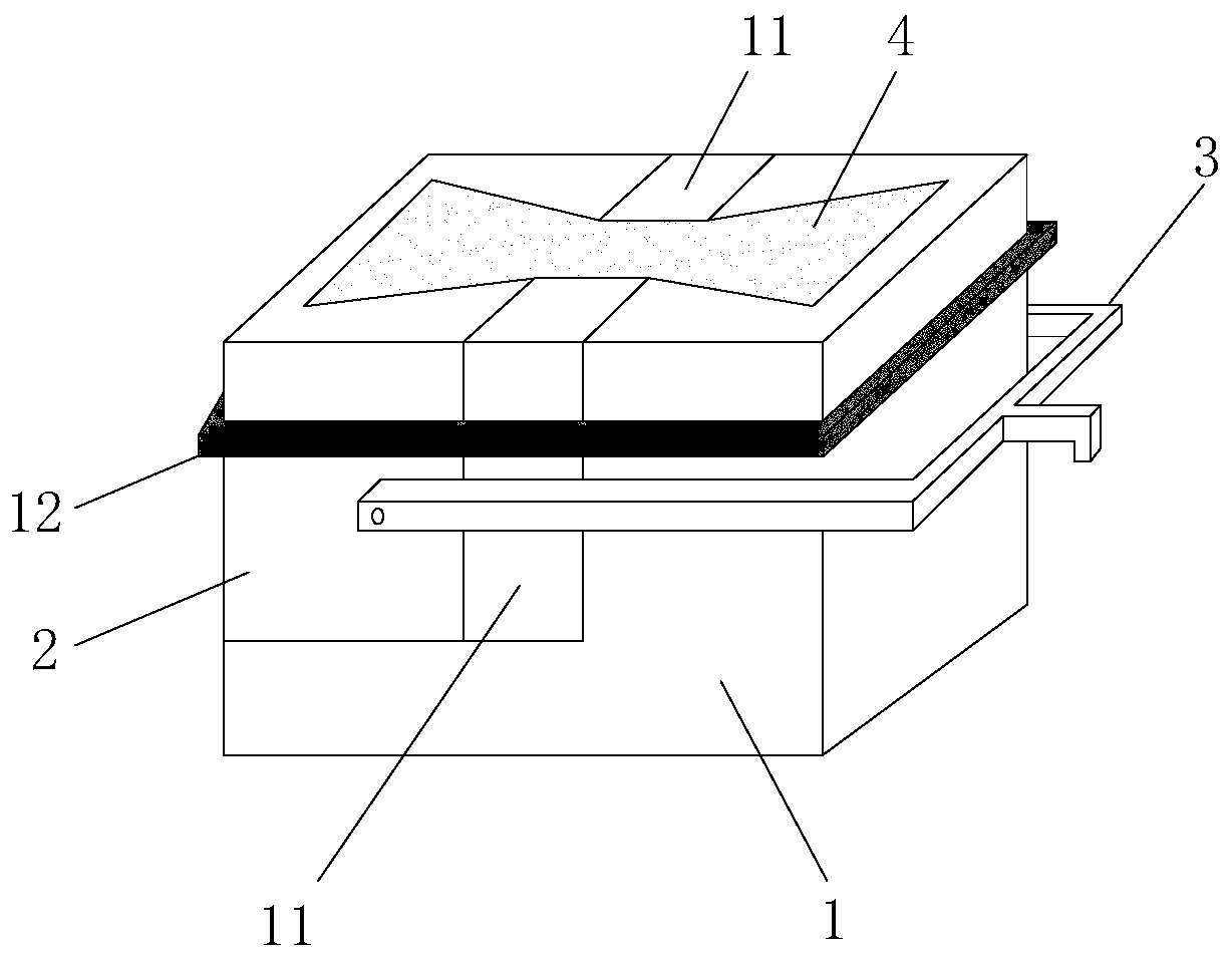
[0027] Such as Figure 1-2 As shown, this embodiment is a device for measuring the tensile strength of soil using a direct shear instrument, including a first tension box 1, a second tension box 2, a U-shaped bar 3, and the like. The first pull box 1 was type, which can replace the shear box in the traditional direct shear instrument and fix it on the first base 6 to ensure that the two move synchronously; one side of the first base 6 is provided with a force rod 5, which can only be used under the restriction of the ball 7 Parallel movement; the second tension box 2 is located on the upper left of the first tension box 1, and can be separated from each other under the action of external force to form a separate tension box; one end of the U-shaped rod 3 passes through the first tension box 1 and connects with the ...


PUM


Abstract

The invention discloses a device and method for measuring the tensile strength of soil by using a direct shear instrument, comprising a first tension box, a second tension box, a U-shaped bar, soil samples, etc., the first tension box and the second tension box are placed On the first base provided with balls; one end of the U-shaped rod is fixedly connected to the second tension box, and the other end is in contact with the measuring ring fixed on the second base and provided with a micrometer inside. With the help of the traditional direct shear instrument, the present invention converts the external force into the tension applied to both ends of the soil sample through the separate tension box, and realizes the integrated operation of sample loading, stretching, and measurement, and the steps are simple and cost-effective. It can accurately measure the tensile strength of the soil; the "dumbbell"-shaped soil sample with a narrow middle and wide ends eliminates the necessary clamps and lugs at both ends of the mold in the existing one-way tensile device, and overcomes the influence of the soil sample's own weight And the end effect produced by the existing device on the two ends of the sample.

Description

technical field [0001] The invention belongs to the field of geotechnical engineering and geotechnical testing, and relates to a device and method for measuring the tensile strength of soil by using a direct shear instrument, which is suitable for measuring the tensile strength of soil in dykes, roads, slopes, etc. Provide data for stability design and prevention of cracks. Background technique [0002] Traditional soil mechanics believes that the soil can only bear the compressive stress, and often ignores the tensile stress of the soil. In recent years, with the emergence of more and more engineering problems, it is proved that the tensile strength of the soil plays an important role in the stability of the actual engineering soil, such as the hydraulic splitting of the core wall of the earth-rock dam in the hydraulic engineering, the road engineering Cracks in the subgrade, sliding of the slope, shrinkage cracks in the unsaturated soil foundation, etc. Therefore, the ac...

Claims


Application Information

Patent Timeline
Patent Type & Authority Patents(China)
IPC IPC(8): G01N3/08
CPCG01N3/08
Inventor 吉恩跃朱俊高刁红国张灿虹陆阳洋郭万里包孟碟蒋明杰
Owner HOHAI UNIV
Learn More