
Harmonic responsibility distinguishing method considering background harmonic voltage

A background harmonic and harmonic technology, which is applied in the measurement of electricity, measurement of electrical variables, spectrum analysis/Fourier analysis, etc., can solve the problems of unclear harmonic responsibility, inability to carry out responsibility penalties, and power quality disputes.

Active Publication Date: 2017-09-15
XIAN UNIV OF SCI & TECH
View PDF5 Cites 13 Cited by
  • Summary
  • Abstract
  • Description
  • Claims
  • Application Information

AI Technical Summary

Problems solved by technology

The second category is the division of harmonic responsibilities in a distributed multi-bus system, that is, a network with multiple common connection points. The state estimation theory is mainly used to determine which bus system the harmonic source is located in. It is necessary to accurately grasp the network structure and harmonic impedance during calculation. and the harmonic components of the system, but it is difficult to obtain relevant data in practical applications
The third type is the load impedance method, which can only qualitatively determine whether the user is a harmonic source, but cannot determine the user's harmonic content and harmonic components
Because the harmonic current level at the PCC point cannot represent the real level of harmonics of each user, this will lead to power quality disputes and unclear responsibilities for harmonics. When power quality problems occur, liability penalties cannot be imposed

Method used


Image

  • Harmonic responsibility distinguishing method considering background harmonic voltage
  • Harmonic responsibility distinguishing method considering background harmonic voltage
  • Harmonic responsibility distinguishing method considering background harmonic voltage

Examples


Embodiment Construction

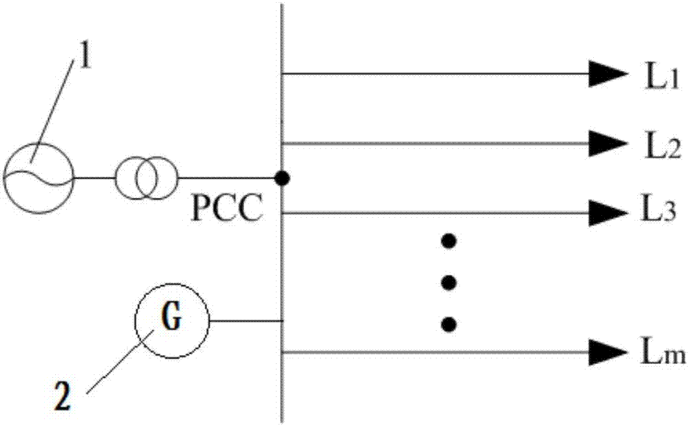
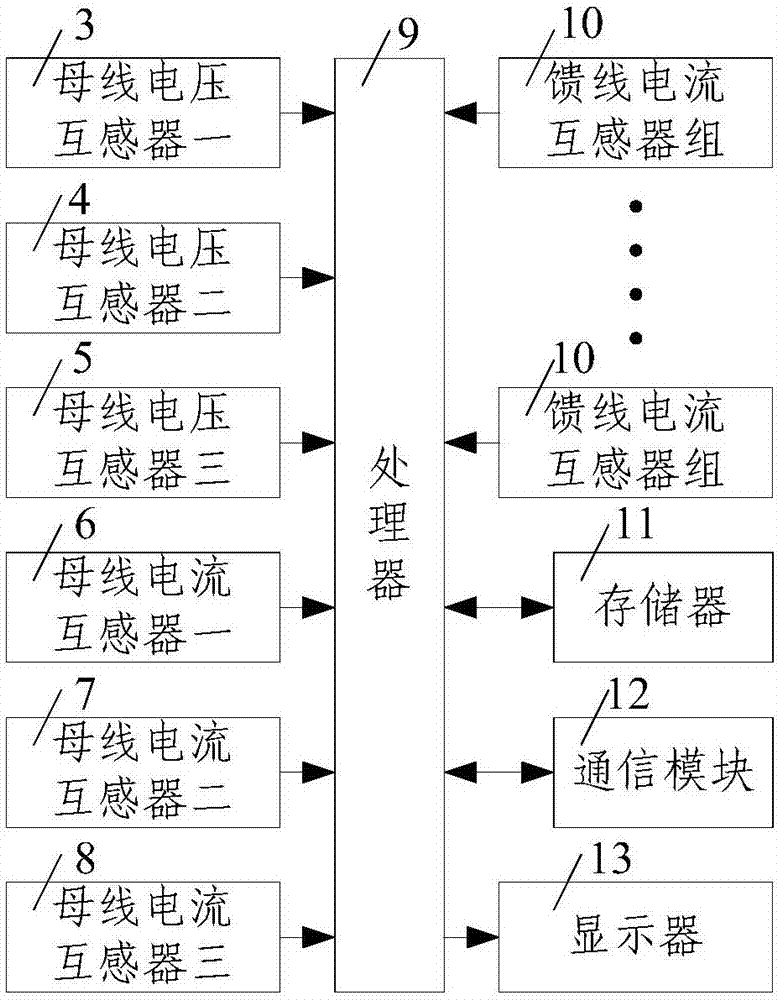
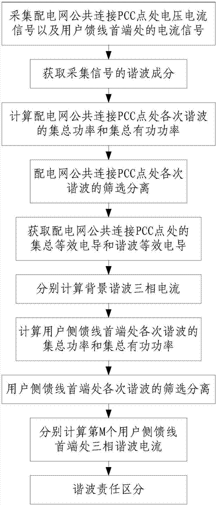
[0059] Such as Figure 1 to Figure 3 As shown, the method for distinguishing the harmonic responsibility of the present invention containing the background harmonic voltage comprises the following steps:

[0060] Step 1. Collect the voltage and current signals at the PCC point of the public connection of the distribution network and the current signal at the head end of the user feeder: collect the phase A voltage u of the PCC point of the public connection of the distribution network PA (t), B-phase voltage u PB (t), C-phase voltage u PC (t), collect the A-phase current i of the common connection PCC point of the distribution network PA (t), B-phase current i PB (t), C-phase current i PC (t), respectively collect the three-phase current i at the head end of m user-side feeders in the distribution network through the feeder current transformer group 10 M.A (t), i M.B (t), i M.C (t), wherein, m and M are positive integers and M=1,2,...,m;

[0061] In this embodiment, in...


PUM


Abstract

The invention discloses a harmonic responsibility distinguishing method considering background harmonic voltage, comprising the following steps: (1) collecting voltage and current signals at a point of common coupling PCC of a distribution network and a current signal at the head end of a user feeder; (2) acquiring the harmonic components of the collected signals; (3) calculating the lumped power and lumped active power of each harmonic at the point of common coupling PCC of the distribution network; (4) screening and separating the harmonics at the point of common coupling PCC of the distribution network; (5) acquiring the lumped equivalent conductance and harmonic equivalent conductance at the point of common coupling PCC of the distribution network; (6) calculating the three-phase current of background harmonic; (7) calculating the lumped power and lumped active power of each harmonic at the head end of the user feeder; (8) screening and separating the harmonics at the head end of the user feeder; (9) calculating the three-phase harmonic current of the feeder at an Mth user side; and (10) distinguishing the harmonic responsibility. The harmonic responsibility can be precisely located to each user, the content and component of each user's harmonic can be accurately calculated, and fair punishment can be carried out.

Description

technical field [0001] The invention belongs to the technical field of harmonic responsibility distinction, and in particular relates to a harmonic responsibility distinction method including background harmonic voltage. Background technique [0002] In recent years, distributed power sources such as solar power and wind power are directly connected to the distribution network, which brings new harmonic problems to the distribution network, which increases the background harmonic voltage on the system side of the distribution network, while the existing The method for distinguishing harmonic responsibilities does not take into account the background harmonic voltage, which will lead to large errors in the quantification of harmonic responsibilities. A large number of equipment containing power electronic devices is connected to the distribution network, which also distorts the power supply current, and the harmonic pollution is becoming more and more serious. Harmonic curre...

Claims


Application Information

Patent Timeline
Patent Type & Authority Applications(China)
IPC IPC(8): G01R23/16G01R31/08
CPCG01R23/16G01R31/086G01R31/088
Inventor 王清亮上官尧王雷刚秦洁刘新茹郭帅吕栋平
Owner XIAN UNIV OF SCI & TECH
Learn More