Motor zero-position calibration system and method

A technology of zero calibration and calibration method, which is applied in the direction of motor generator testing, electrical measurement, and electrical variable measurement, and can solve problems affecting motor performance, theoretical angle deviation, and influence

Inactive Publication Date: 2017-09-15
CHERY AUTOMOBILE CO LTD
View PDF10 Cites 6 Cited by
  • Summary
  • Abstract
  • Description
  • Claims
  • Application Information

AI Technical Summary

Problems solved by technology

For oil-cooled motors, due to factors such as the viscosity of the cooling oil, the positioning angle of the motor rotor is likely to deviate from the theoretical angle, which affects the determination of the relative angle between the rotor position detected by the angular position sensor and the actual rotor magnetic field, which in turn affects to motor performance

Method used


Image

  • Motor zero-position calibration system and method
  • Motor zero-position calibration system and method

Examples


Embodiment Construction

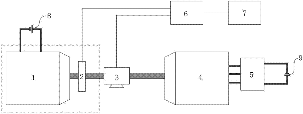
[0025] Such as figure 1 As shown, the motor zero calibration system connects the standard machine 4 with the output shaft of the measured motor 1. The standard machine 4 generally uses a standard motor or dynamometer. The motor position sensor 2 is rigidly connected to the shaft of the measured motor 1. The sensor 2 is used to output the angle signal of the motor rotor. The connection mode and position angle of the measured motor 1 and the position sensor 2 should be consistent with the actual installation. The measured motor 1 and the position sensor 2 can be connected firmly according to the use requirements, as a Perform zero calibration as a whole.

[0026] The output shaft of the standard machine 4 is equipped with a torque sensor 3, the torque measuring instrument is used to measure the actual torque on the motor shaft, the standard machine 4 is used to drive the measured motor 1 to rotate at a constant speed, and the signal processing module 6 is used to receive the motor p...


PUM


Abstract

The invention discloses a motor zero-position calibration system. A first DC power source supplies power to a detected motor, an output shaft of the detected motor is in rigid connection with a position sensor, the position sensor outputs an angle signal of the detected motor to a signal processing module, the system is provided with a standard machine used for driving the detected motor to rotate at constant speed, the standard machine is connected with the output shaft of the detected motor, an output shaft of the standard machine is provided with a torque sensor, andthe torque sensor outputs a torque signal to the signal processing module. The motor zero-position calibration system and the motor zero-position calibration method are applied to zero-position calibration of an oil-cooling motor, and especially can be applied to a hybrid power vehicle integrated oil-cooling motor. Different from the traditional zero-position calibration process that a motor rotor is positioned at a position where the minimal force is applied to a motor rotor, resulting in imprecise positioning, the motor zero-position calibration system and the motor zero-position calibration method simulate the actual operating process of motor magnetic field directional control, can avoid the influence of cooling oil on zero-position calibration precision through identifying the position where the minimum force is applied to the motor rotor, and realize the precise and efficient zero-position calibration.

Description

Technical field [0001] The invention relates to the technical field of automobile drive motors, in particular to a zero calibration method of an integrated oil-cooled motor. Background technique [0002] At present, the types of drive motors used in new energy vehicles include AC asynchronous induction motors, permanent magnet synchronous motors, DC motors, DC brushless motors, etc. Among them, permanent magnet synchronous motors have the most specific applications because of their high efficiency and high power density. widely. [0003] Controlling permanent magnet synchronous motors is relatively complicated, and the most commonly used is vector control, that is, field-oriented control. This control method needs to accurately obtain the actual angle of the motor rotor. In practical applications, there is usually a deviation between the rotor position detected by the angular position sensor of the motor and the actual rotor magnetic field position. The zero calibration process o...

Claims


Application Information

Patent Timeline
Patent Type & Authority Applications(China)
IPC IPC(8): G01R31/34
CPCG01R31/346
Inventor 任宗丹
Owner CHERY AUTOMOBILE CO LTD
Why Eureka
Try Eureka