Electric push rod

A technology of electric push rod and transmission screw, applied in the direction of using feedback control, etc., can solve the problems of limited precision, sunlight deviation, large error of electric push rod return to zero accuracy, etc., to achieve rapid response, guaranteed accuracy, and good sensitivity Effect

Pending Publication Date: 2017-09-15
ZHEJIANG JIECHANG LINEAR MOTION TECH
View PDF5 Cites 2 Cited by
  • Summary
  • Abstract
  • Description
  • Claims
  • Application Information

AI Technical Summary

Problems solved by technology

[0003] However, with the development of solar technology, solar thermal power generation technology is an emerging solar energy utilization technology after photovoltaic power generation. Its principle is to gather the energy of direct solar light in a focused way through a large number of heliostats. In this collection method, the role of the heliostat is more critical. In order to improve the efficiency of reflecting sunlight by the heliostat, the electric push rod has been used as the driving device of the heliostat, but the traditional electric push rod is limited due to the The switch usually adopts the contact type. This kind of limit switch has limited precision, and after long-term use, the error between the parts will become larger after the wear and tear between the parts, which often leads to the low precision of the electric push rod. Because the distance between the heliostat and the collection tower is very Once the zero-return accuracy error of the electric push rod is large, the sunlight reflected by the heliostat will deviate greatly, resulting in the acquisition tower being unable to collect the sunlight reflected by the heliostat

Method used


Image

  • Electric push rod
  • Electric push rod
  • Electric push rod

Examples


Embodiment 1

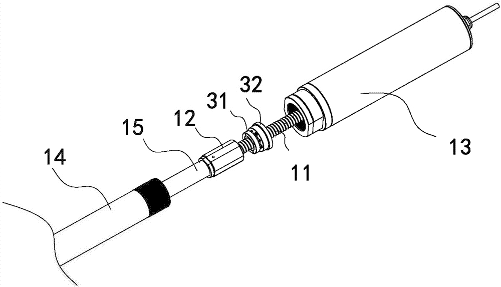
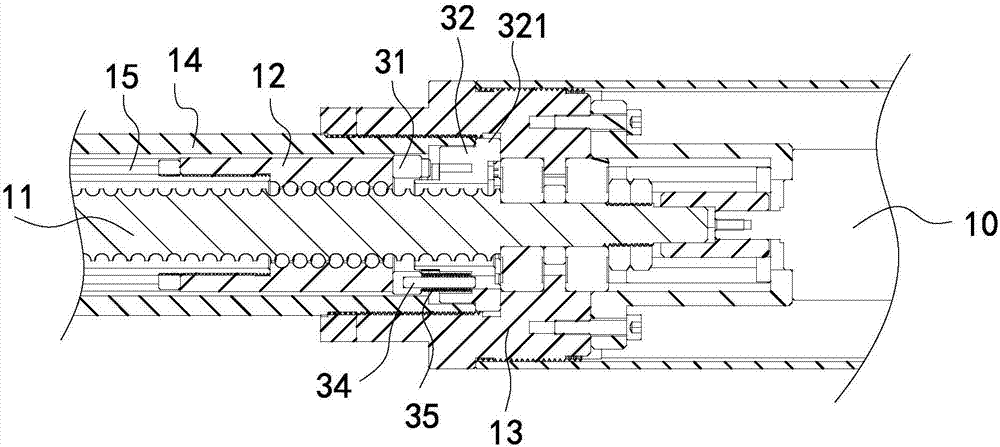
[0033] Such as Figure 1 to Figure 8 As shown, this embodiment shows an electric push rod for solar thermal power generation. This embodiment is mainly used in solar thermal power generation technology to drive heliostats. Of course, it can also be used for other pairs of electric push rods. In the field of high precision, the main structure of the electric push rod in this embodiment includes a motor 10, the motor 10 is connected with a drive screw 11, the drive screw 11 is connected with a nut 12, and the motor 10 is installed in the base 13 , the base 13 is fixedly connected with the outer tube 14, and the nut 12 is fixedly connected with the inner tube 15, when the motor 10 drives the drive screw 11 to rotate, the nut 12 and the drive screw 11 move relatively, specifically in the drive screw 11 The reciprocating movement between the two positions on the nut 12 is a reciprocating movement between an initial position and an extreme position. Overall, the relative movement b...

Embodiment 2

[0051] The difference between this embodiment and Embodiment 1 is that there is no fixed seat in this embodiment, the photoelectric sensor is directly fixed on the base, and the touch panel is also installed on the base, and is installed in a sliding fit with the base. The structure is to set a chute on the base, let the touch plate slide and install in the chute, after the photoelectric sensor is installed on the base, cover it with a protective cover to prevent oil, of course, the protective cover is also set accordingly There is a first opening as in embodiment 1, for the trigger projection to stretch in or out.


PUM


Abstract

The invention discloses an electric push rod and belongs to the technical field of linear driving. The electric push rod includes a motor, a drive screw and a nut. The motor drives the drive screw to rotate so as to drive the nut to reciprocatingly move between an initial position and an extreme position. The electric push rod also includes a photoelectric sensor and a contact plate which is intended for triggering the photoelectric sensor. When the nut retreats to the initial position, the nut drives the contact plate to move towards the photoelectric sensor. According to the invention, the electric push rod is advantaged in that the electric push rod can precisely sense the initial position of the nut and has high return-to-zero precision. According to the invention, the electric push rod is intended for driving a heliostat in solar thermal power generation.

Description

【Technical field】 [0001] The invention relates to an electric push rod, which belongs to the technical field of linear transmission. 【Background technique】 [0002] Electric push rods, generally also called linear actuators, their main working principle is to drive the transmission screw to rotate through the motor, and the nut is set on the transmission screw, which drives the nut to reciprocate when the transmission screw rotates, and the traditional electric push rod will set the limit Switch, when the nut is in the initial position or the limit position, the limit switch will be triggered. Traditional electric push rods are generally used in furniture, office, kitchen and bathroom, and the requirements for the telescopic accuracy of the electric push rod are low, so the limit switch accuracy Also relatively low. [0003] However, with the development of solar technology, solar thermal power generation technology is an emerging solar energy utilization technology after p...

Claims


Application Information

Patent Timeline
IPC IPC(8): G05D3/12
CPCG05D3/12
Inventor 陆小健张甲程云山李博
Owner ZHEJIANG JIECHANG LINEAR MOTION TECH
Why Eureka
Try Eureka