
Wound-stacked battery

A stacked battery technology, applied in secondary batteries, secondary battery manufacturing, circuits, etc., can solve the problems of battery safety not being guaranteed, battery cycle performance deterioration, affecting long-term characteristics of batteries, etc., to reduce internal short circuits The risk, the theoretical loss reduction, the effect of low loss

Active Publication Date: 2017-09-15
ETRUST POWER ETP GRP LTD
View PDF7 Cites 5 Cited by
  • Summary
  • Abstract
  • Description
  • Claims
  • Application Information

AI Technical Summary

Problems solved by technology

[0003] The winding type, laminated type, bag-making type, and stacked-folded battery structure have the following advantages and disadvantages: (1) The winding type structure is manufactured by densely winding long-sheet negative electrodes and long-sheet positive electrodes. formula structure, as a result, the battery structure is circular or elliptical in cross-section, the stress due to the expansion and contraction of the electrodes during charging and discharging of the battery is accumulated in the battery structure, and when the stress accumulation exceeds a certain limit, the battery structure will Deformation, the deformation of the battery structure leads to uneven gaps between the electrodes, the cycle performance of the battery will deteriorate sharply, and the safety of the battery cannot be guaranteed due to the short circuit inside the battery; (2) the laminated structure passes through sequentially Stacking multiple unit negative electrodes and multiple unit positive electrodes to manufacture a stacked battery structure requires a lot of time and effort to perform sequential stacking processes, resulting in low production efficiency in this process; (3) bag-making structure, compared to lamination (4) The stacking-folding structure has high production efficiency and stable structure, but the difference between electrolyte layers will affect the long-term characteristics of the battery

Method used


Image

  • Wound-stacked battery
  • Wound-stacked battery
  • Wound-stacked battery

Examples


Embodiment 1

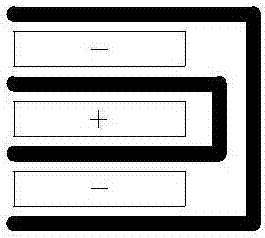
[0058] The winding structure unit has two different structures, figure 1 It is the structure of the winding structure unit one before winding, with two layers of diaphragms in parallel, the negative pole piece is set in the middle of the two layers of diaphragms, and the positive pole piece is spaced above the diaphragm, and the winding structure unit one after winding 0.5 turns structured as figure 2 As shown, the structure of the winding structure unit 1 is separator / negative electrode / diaphragm / positive electrode / diaphragm / negative electrode / diaphragm, image 3 It is the structure before the second winding of the winding structure unit. Two layers of separators are arranged in parallel. The negative pole piece is set in the middle of the two layers of membranes. The structure of the second winding structure unit is as follows Figure 4 As shown, the structure of the winding structure unit 2 is positive electrode / diaphragm / negative electrode / diaphragm / positive electrode / d...

Embodiment 2

[0060] The difference from Example 1 lies in the difference of the winding structure unit, the winding structure unit has two different structures, Figure 6 It is a winding structure unit-the structure before winding, with two layers of diaphragms in parallel, the negative pole piece is set in the middle of the two layers of diaphragms, and the positive pole pieces are respectively arranged above the first layer of diaphragm and below the second layer of diaphragm, winding The number of turns can be 0.5*N (N is an odd number), and the winding structural unit after winding 1.5 turns has a structure such as Figure 7 As shown, the structure of the winding structure unit 1 is separator / negative electrode / diaphragm / positive electrode / diaphragm / negative electrode / diaphragm / positive electrode, such as Figure 8 The structure of the winding structure unit 2 shown is diaphragm / negative electrode / diaphragm. The two winding structure units 1 are stacked in sequence. After stacking, the...

Embodiment 3

[0062] The difference with embodiment 1 is that the winding structure unit is different, and the winding structure unit has two different structures, such as Figure 10 As shown, the structure of the wound structure unit 1 is separator / negative electrode / separator / positive electrode, such as Figure 11 As shown, the structure of the wound structure unit 2 is separator / negative electrode / separator, such as Figure 12 As shown, four sets of winding structural units are stacked in sequence, and after stacking, the two sides are respectively the separator and the positive electrode sheet, and the outermost layer is the side of the positive electrode sheet, and a set of winding structural units are stacked on this side to form a battery electrode group.


PUM


Abstract

The invention discloses a wound-stacked battery which comprises a cell. The cell is formed by stacking wound structural units, each wound structural unit comprises a horizontally-arranged diaphragm, an anode piece and a cathode piece, each anode piece and the corresponding cathode piece are spaced by the corresponding diaphragm and integrally wound to form the corresponding wound structural unit, and number of winding turns is 0.5*N, wherein N is a positive integer; each formed wound structural unit is any interceptible part of a unit with cathode / diaphragm / anode / diaphragm / cathode / diaphragm / anode / diaphragm / cathode / diaphragm / anode / diaphragm / cathode alternately repeated, multiple wound structural units are stacked to form a battery pole group, each anode piece and the corresponding cathode piece are arranged on two sides separated by the corresponding diaphragm in the battery pole group to form a battery pair, the outermost layer of the battery pole group is one diaphragm, and the second outermost layer is one cathode piece. The wound-stacked battery has the advantages of being free of circular-arc area, saving of raw materials, low in loss, uniform in circulation and expansion, high in preparation efficiency, uniform in electrolyte distribution and high in structural stability.

Description

technical field [0001] The invention relates to a battery, in particular to a winding-stacked battery. Background technique [0002] Nowadays, the use of lithium-ion batteries in power tools is growing explosively, and the cost, production efficiency, long-term life and consistency of power batteries are in urgent need of rapid breakthroughs, so the research on the structure of battery components is the top priority. The current structure of battery components includes winding type, laminated type, bag-making type, stacking-folding type and other structures: the winding type structure is to separate the continuous positive electrode sheet and negative electrode sheet through the separation film; In the type structure, specific structural units are stacked continuously and separated by a separation membrane; the bag-making structure is a structure in which the negative electrode is first bagged in a separator bag, and then stacked layer by layer; stacking-folding In the form...

Claims


Application Information

Patent Timeline
Patent Type & Authority Applications(China)
IPC IPC(8): H01M10/04H01M10/0587
CPCH01M10/04H01M10/0587Y02E60/10Y02P70/50
Inventor 程君刘灿柳听前王玉虎金江敏
Owner ETRUST POWER ETP GRP LTD
Learn More