Motor package aluminum rotor structure

A technology of rotor structure and aluminum cladding, applied in the direction of magnetic circuit shape/style/structure, mechanical equipment, machine/engine, etc., can solve problems such as centrifugal inertia force can not offset each other, accelerate bearing wear, shorten mechanical life, etc., to achieve saving The time to adjust the direction of the fan blades, ensure the dynamic balance, and reduce the overall vibration effect

Pending Publication Date: 2017-09-15
FANS TECH ELECTRIC CO LTD
View PDF11 Cites 0 Cited by
  • Summary
  • Abstract
  • Description
  • Claims
  • Application Information

AI Technical Summary

Problems solved by technology

[0004] In the existing rotor structure, due to uneven material or blank defects, errors in processing and assembly (air holes on the surface of the material, non-concentricity of the steel ring and the rotor body), even the design has an asymmetrical geometric shape When the rotor structure is rotating, the centrifugal inertial force generated by each tiny particle on it cannot cancel each other out. The centrifugal inertial force acts on the motor through the bearing, causing vibration, noise, and accelerated bearing wear. The mechanical life is shortened, and it can cause destructive accidents in severe cases

Method used


Image

  • Motor package aluminum rotor structure
  • Motor package aluminum rotor structure
  • Motor package aluminum rotor structure

Examples


no. 1 example

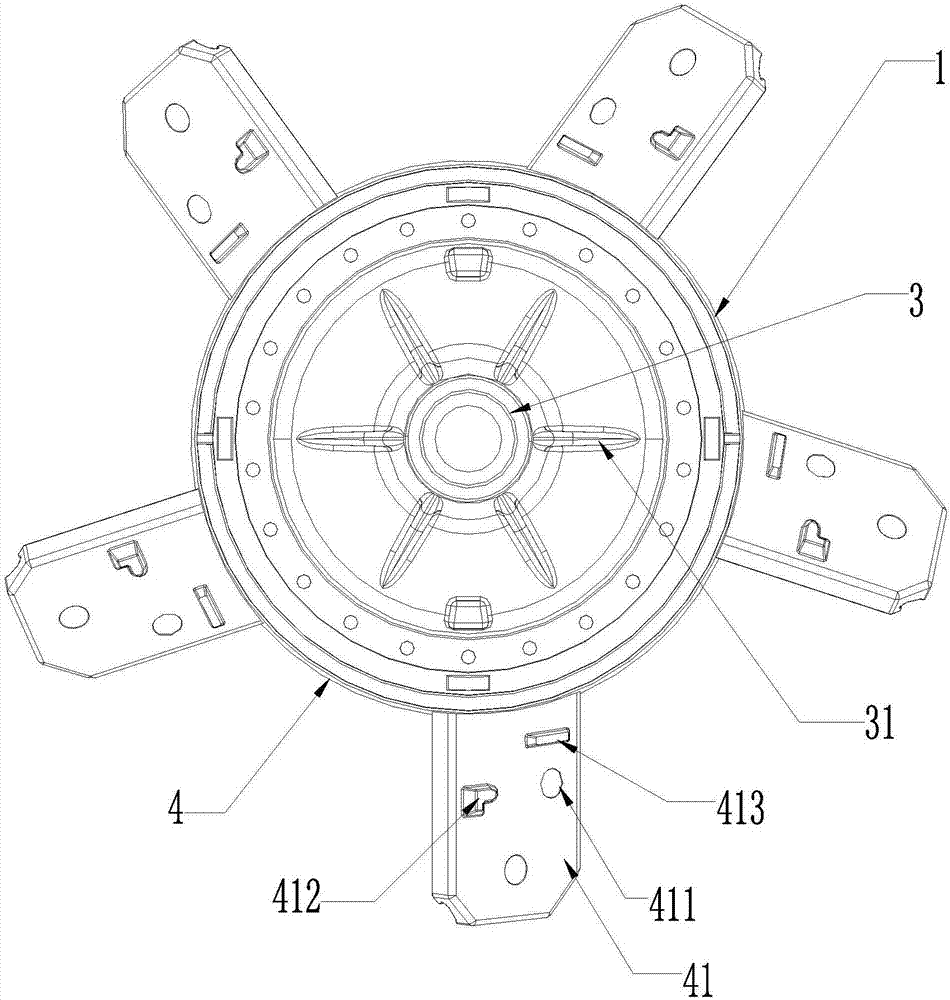
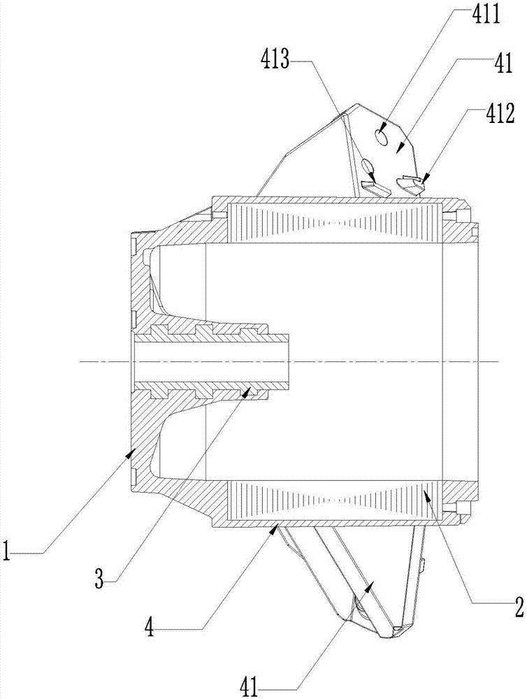
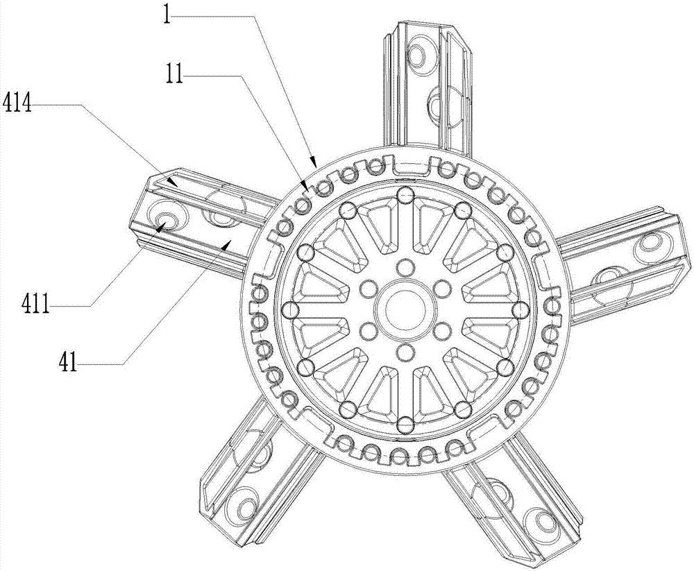
[0029] Such as Figure 1-5 As shown, in order to achieve the above purpose, the technical solution adopted by the present invention is as follows: The present invention discloses an aluminum-clad rotor structure for a motor, including a rotor body 1 and a flange structure 41, and the flange structure 41 is evenly and symmetrically arranged on the rotor body On the side wall of the outer circle 4 of 1, the flange structure 41 is used to disassemble and fix the fan blade 5, and the rotor body 1 and the flange structure 41 are integrally formed by a die-casting process. The rotor structure is produced through an integrated die-casting molding process. The rotor structure is an integral structure, which minimizes the beating problem caused by the interference fit of the steel ring to the outer circle of the rotor body, and at the same time solves the air hole problem on the surface of the rotor structure.

[0030] Such as figure 1 with 6 As shown, in the first embodiment of the ...

no. 2 example

[0036]This embodiment only describes the difference from the above embodiment, and other technical features are the same as the above embodiment. In the second embodiment of the present invention, the mounting area on the front of the flange structure 41 is provided with several positioning holes and threaded holes 411 for positioning and fixing the fan blade 5 . Several positioning protrusions and threaded through holes 511 are provided on the mounting surface 51 of the fan blade 5 mounted on the rotor structure.


PUM


Abstract

The invention discloses a motor package aluminum rotor structure which comprises a rotor body and a flange structure which is evenly symmetrically arranged on the outer circumferential side wall of the rotor body. The flange structure is used for disassembling and fixing fan blades. The rotor body, the steel ring and the flange structure are integrally die-casted. A number of positioning studs and threaded holes are arranged in the front of the flange structure to position and fix the fan blades. Reinforcing ribs are arranged on the back of the flange structure. The reinforcing ribs are arranged on the back of the flange structure, and a number of reinforcing ribs are arranged at the bottom of the casing body of the rotor body, so that air holes can be prevented in the formation of the flange structure and the casing body of the rotor body. Stress concentration caused by air holes during a working process can be prevented. The rotor structure is produced through an integral die-casting process, and the problem of beating caused by interference fit of the steel ring and the outer circle of the rotor body is reduced to the greatest extent.

Description

technical field [0001] The invention belongs to the technical field of motors, in particular to an aluminum-clad rotor structure of a motor. Background technique [0002] The rotor structure of the existing motor-driven blades includes the rotor body and the steel ring. The rotor body and the steel ring are manufactured separately. The steel ring is interference-fitted to the outer circle of the rotor body, and then the rotor body and the steel ring are welded to form the rotor structure. drive blades. During the operation of the motor, the rotating shaft drives the rotor body to rotate. Due to the runout of the rotor body, the beating of the steel ring will be larger after the interference fit of the steel ring, and the larger the diameter of the fan blade, the beating of the fan blade will be doubled. Excessive beating of the fan blades will cause the entire fan to vibrate and increase the noise. And because the steel ring is an interference fit on the rotor body, the co...

Claims


Application Information

Patent Timeline
Patent Type & Authority Applications(China)
IPC IPC(8): H02K1/22F04D29/26
CPCH02K1/22F04D29/263
Inventor 陈克荣陈康
Owner FANS TECH ELECTRIC CO LTD
Why Eureka
Try Eureka