
Model predictive control method and device for npc three-phase three-level grid-connected inverter

A technology of model predictive control and model prediction, which is applied in the direction of output power conversion devices, electrical components, and conversion of AC power input to DC power output, etc., which can solve the problem that the three-phase network current THD value is large and the DC side cannot be well suppressed. Point voltage fluctuations, damage to switching devices, etc.

Active Publication Date: 2019-08-23
NANJING UNIV OF SCI & TECH
View PDF2 Cites 0 Cited by
  • Summary
  • Abstract
  • Description
  • Claims
  • Application Information

AI Technical Summary

Problems solved by technology

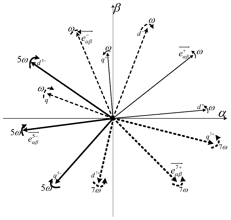
[0003] However, most of the actual power grid conditions are not ideal, except for the fundamental frequency positive sequence component e in the non-ideal grid voltage + In addition, it also contains the fundamental frequency negative sequence component e - , 5 times frequency negative sequence component e 5- and the 7-fold positive sequence component e 7+ etc. At this time, the NPC three-phase three-level grid-connected inverter control method based on ideal grid conditions will inevitably lead to low-quality power entering the grid
At the same time, the midpoint voltage suppression method on the DC side of the NPC three-phase three-level grid-connected inverter based on ideal grid conditions cannot well suppress the fluctuation of the midpoint voltage on the DC side, which may easily cause damage to the switching devices and three-phase grid-connected inverters. Problems such as large current THD value

Method used


Image

  • Model predictive control method and device for npc three-phase three-level grid-connected inverter
  • Model predictive control method and device for npc three-phase three-level grid-connected inverter
  • Model predictive control method and device for npc three-phase three-level grid-connected inverter

Examples


Embodiment 1

[0157] The grid-connected control goal of Embodiment 1 is to eliminate the 2, 4, and 8 fluctuations in active power, according to Figure 8 The NPC three-phase three-level inverter grid-connected system based on model predictive control under non-ideal grid conditions has been simulated. The specific parameters are shown in Table 1. The simulation result of embodiment 1 is as Figure 9 as shown, Figure 9 (a)~(d) are the simulation results of the three-phase grid incoming current, the midpoint voltage of the DC side, the grid instantaneous active power, and the grid instantaneous reactive power, respectively, from Figure 9 It can be seen that the model predictive control under non-ideal grid conditions can effectively eliminate the 2nd, 4th, and 8th fluctuations of the grid-connected active power, and at the same time suppress the midpoint voltage of the DC side.

[0158] Table 1 Simulation parameters

[0159] Fundamental frequency positive sequence component amp...

Embodiment 2

[0161] The goal of grid-connected control in Example 2 is to eliminate 2, 4, and 8 fluctuations in reactive power, and the specific parameters are modified from Table 1. P * 0 =500W, Q * 0 =10kVar, the other parameters remain unchanged. The simulation result of embodiment 2 is as Figure 10 as shown, Figure 10 (a)~(d) are the simulation results of the three-phase grid incoming current, the midpoint voltage of the DC side, the grid instantaneous active power, and the grid instantaneous reactive power, respectively, from Figure 10 It can be seen from the figure that the model predictive control under non-ideal power grid conditions can effectively eliminate the 2nd, 4th, and 8th fluctuations of the grid-connected reactive power, and at the same time suppress the midpoint voltage of the DC side. In this embodiment, a large amount of reactive power buffering is required, so The fluctuation of the voltage amplitude of the capacitor voltage on the DC side becomes larger, resu...

Embodiment 3

[0163] The grid-connected control goal of Embodiment 3 is to realize the sinusoidal and balanced three-phase grid-connected current, and the specific parameters are shown in Table 1. The simulation result of embodiment 3 is as Figure 11 as shown, Figure 11 (a)~(d) are the simulation results of the three-phase grid incoming current, the midpoint voltage of the DC side, the grid instantaneous active power, and the grid instantaneous reactive power, respectively, from Figure 11 It can be seen that the model predictive control under non-ideal grid conditions can effectively realize the sinusoidal and balanced three-phase grid current, while suppressing the midpoint voltage of the DC side.

[0164] In summary, the model predictive control method adopted in the present invention achieves ideal control effects for grid-connected control of NPC three-phase three-level inverters under non-ideal grid conditions.


PUM


Abstract

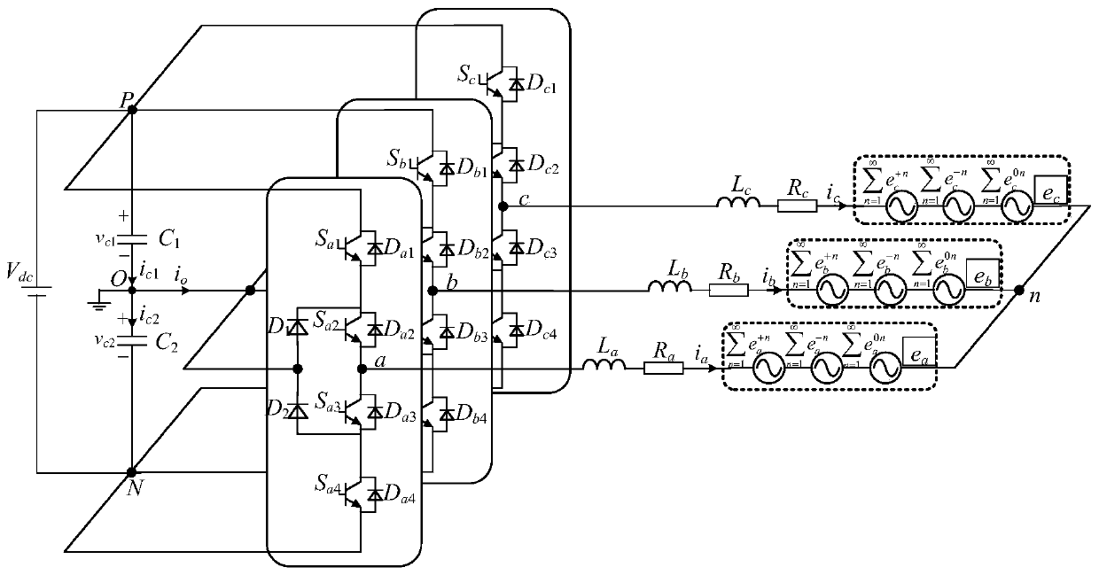
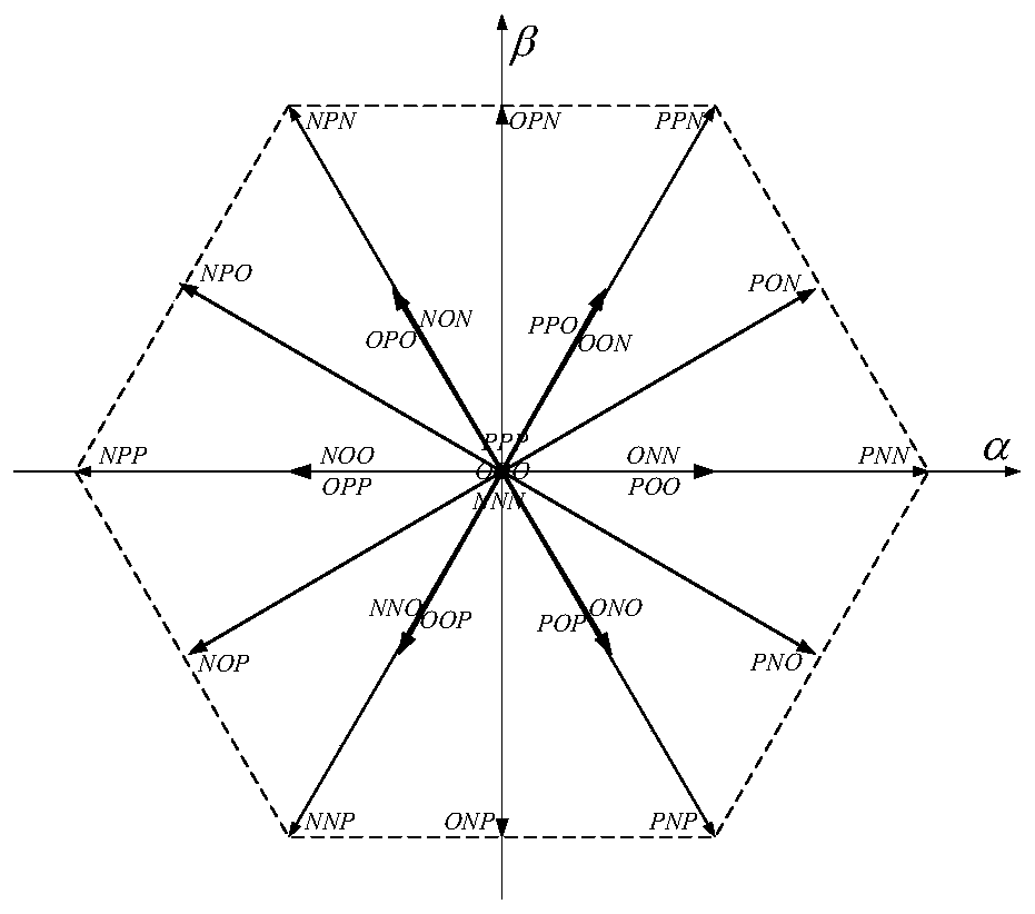
The invention discloses a model prediction control method and apparatus of a NPC three-phase three-level grid-connected inverter. The method includes the following steps: conducting Clark transformation on sampling values of a three-phase networking current and a three-phase grid voltage; using a DOSGI-SPLL module and a grid voltage feature value extraction module to obtain a grid voltage feature value which is required in computing a networking reference current; using the two-step prediction method to conduct tracking control and DC side neutral-point voltage suppression on the three-phase networking current so as to compensate the delay which is caused by sampling and computing. The apparatus includes a master power circuit, a control circuit and a detection circuit. The master power circuit includes a NPC three-phase three-level inverter and an L-shaped low pass filter. The detection circuit includes a networking current detection circuit, a grid voltage detection circuit and a DC side neutral-point voltage detection circuit. According to the invention, the method can realize excellent grid-connected control of the NPC three-phase three-level inverter under non-ideal grid conditions, can greatly increase networking electricity quality and at the same time effectively suppresses fluctuation of DC side neutral-point voltage.

Description

technical field [0001] The invention relates to the technical field of DC-AC converters of electric energy conversion devices, in particular to a model predictive control method and device for an NPC three-phase three-level grid-connected inverter. Background technique [0002] NPC (Neutral Point Clamped) three-phase three-level grid-connected inverter acts as an energy conversion interface in a distributed grid-connected power generation system, and its working status has a great impact on the quality of power entering the grid. Under ideal grid conditions, the grid voltage only contains the fundamental frequency positive sequence component e + , the existing NPC three-phase three-level grid-connected inverter control methods are relatively mature, such as PI control, PR control, hysteresis control and so on. [0003] However, most of the actual power grid conditions are not ideal, except for the fundamental frequency positive sequence component e in the non-ideal grid vol...

Claims


Application Information

Patent Timeline
Patent Type & Authority Patents(China)
IPC IPC(8): H02M7/487
Inventor 吕建国马丙辉王纪东姚凯季振东
Owner NANJING UNIV OF SCI & TECH
Learn More