Eureka AIR delivers breakthrough ideas for toughest innovation challenges, trusted by R&D personnel around the world.

Hole punching device for circuit boards

A technology of punching device and circuit board, which is applied in the directions of printed circuit, printed circuit manufacturing, electrical components, etc., can solve problems such as waste, and achieve the effect of saving resources and simplifying the structure

Active Publication Date: 2019-01-25
TAICANG MIX MACHINERY EQUIP CO LTD
View PDF3 Cites 0 Cited by
  • Summary
  • Abstract
  • Description
  • Claims
  • Application Information

AI Technical Summary

Problems solved by technology

[0003] In the prior art, circuit boards are usually processed into perforated boards in batches. Although this method has high drilling efficiency, the debris generated during the drilling process is collected manually. After collection, it is usually It is directly wasted, but the circuit board material is non-toxic and harmless and can be used to make various handicrafts or other finished products, so the applicant proposed a solution to deal with circuit board scraps

Method used


Image

  • Hole punching device for circuit boards
  • Hole punching device for circuit boards
  • Hole punching device for circuit boards

Examples


Embodiment Construction

[0017] The present invention will be described in further detail below by means of specific embodiments:

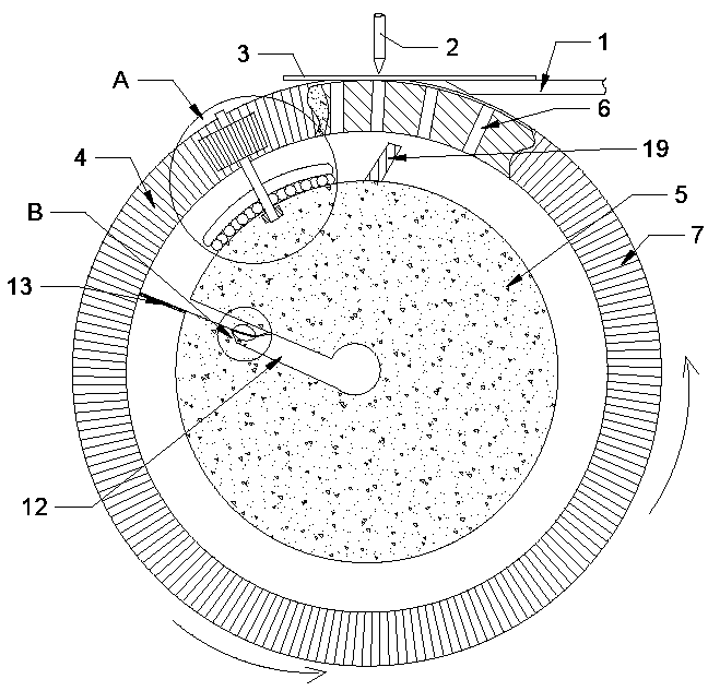
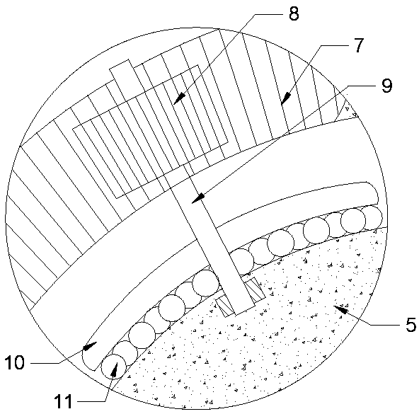
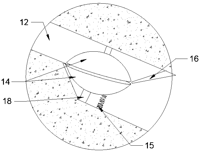
[0018] The reference signs in the drawings of the description include: conveyor belt 1, drill bit 2, circuit board 3, processing ring 4, processing table 5, through hole 6, ring tooth surface 7, gear 8, movable shaft 9, base plate 10, ball 11, Pipeline 12, guide plate 13, arc-shaped disc 14, electromagnet 15, nozzle 16, annular channel 17, support shaft 18, baffle plate 19.

[0019] The embodiment is basically as attached figure 1 Shown: a punching device for circuit boards, including a frame, a drilling mechanism, a grouping mechanism and a conveyor belt 1 between the drilling mechanism and the grouping mechanism, the drilling mechanism includes a reciprocating drill bit 2;

[0020] as attached figure 2 The agglomeration mechanism is located below the drill bit 2. The agglomeration mechanism includes a processing ring 4 and a circular processing table 5. The processin...


PUM


Abstract

The invention relates to the machining field, particularly to a punching apparatus used for a circuit board. The punching apparatus comprises a rack, a drilling mechanism, a clustering mechanism and a conveyor belt positioned between the drilling mechanism and the clustering mechanism; the clustering mechanism is positioned below a drill bit; the clustering mechanism comprises a machining ring rotationally connected with the rack and a machining table fixedly connected with the rack; the machining table is coaxially mounted in the machining ring; through holes are uniformly distributed in the circumferential direction of the machining ring, and an annular through groove is also formed in the machining ring; an annular tooth surface is arranged on one side of the annular through groove; a pipeline is radially arranged in the machining table; the pipeline is positioned on the lower side of a movable shaft; a guiding plate which extends to the outside is arranged on the inlet of the pipeline; arc-shaped plates are rotationally connected with the upper and lower sides in the pipeline respectively; and the two arc-shaped plates are oppositely arranged with opposite rotation directions. By implementation of the above-mentioned technical scheme, an effect of disposing produced chippings in the punching process of the circuit board can be achieved.

Description

technical field [0001] The invention relates to the field of processing, in particular to a circuit board processing device. Background technique [0002] The circuit board is made of high-quality bleached wood paper and cotton linter paper as reinforcement, and the phenolic resin produced by the reaction of high-purity, fully synthetic petrochemical raw materials is used as the resin adhesive, which is non-toxic and non-toxic. Harmful. Because of its characteristics of insulation, no static electricity, wear resistance and high temperature resistance, it is used in insulating switches and variable resistors of electronic products, molds for machinery and fixtures on production lines, and is most commonly used for circuit experiments. Perfboard (a type of circuit board). [0003] In the prior art, circuit boards are usually processed into perforated boards in batches. Although this method has high drilling efficiency, the debris generated during the drilling process is col...

Claims


Application Information

Patent Timeline
Patent Type & Authority Patents(China)
IPC IPC(8): H05K3/00B26F1/16
CPCB26F1/16H05K3/00H05K3/0047
Inventor 周楚奎
Owner TAICANG MIX MACHINERY EQUIP CO LTD
Why Eureka
Eureka Blog
Learn More