
Blind plug type liquid cooling module

A blind insertion and liquid cooling technology, which is applied in the direction of cooling/ventilation/heating transformation, electrical components, electrical equipment structural parts, etc., can solve the problems of electromagnetic compatibility performance, heat dissipation performance, quick disassembly performance rejection, and module vibration and shock resistance. Strong, weak anti-salt spray ability and other problems, to achieve the effect of strong resistance to mechanical environment, reduce professional skill requirements, and improve rapid response ability

Inactive Publication Date: 2017-09-15
叶发亮
View PDF5 Cites 10 Cited by
  • Summary
  • Abstract
  • Description
  • Claims
  • Application Information

AI Technical Summary

Problems solved by technology

[0018] In view of the above-mentioned problems in the prior art, the purpose of the present invention is to provide a fast plug-in and pull-out capability, ultra-high heat dissipation capability, electromechanical-hydraulic collaborative blind-mating capability, radio-frequency blind-mating capability, high electromagnetic shielding capability, and vibration-shock resistance. Blind-insert liquid flow function module with strong capability, strong anti-salt spray ability, friendly human-machine interface, beautiful appearance, convenient operation and meeting the requirements of military environment, to solve the difficulty of disassembling such modules, low heat dissipation capacity, and anti-corrosion The salt spray ability is not strong, the module's anti-vibration and impact ability is not strong, and the technical problems of the module's electromagnetic compatibility performance, heat dissipation performance, and quick disassembly performance are mutually exclusive

Method used


Image

  • Blind plug type liquid cooling module
  • Blind plug type liquid cooling module
  • Blind plug type liquid cooling module

Examples


Embodiment Construction

[0046] In order to make the object, technical solution and advantages of the present invention clearer, the present invention will be described in detail below in conjunction with the accompanying drawings and specific embodiments.

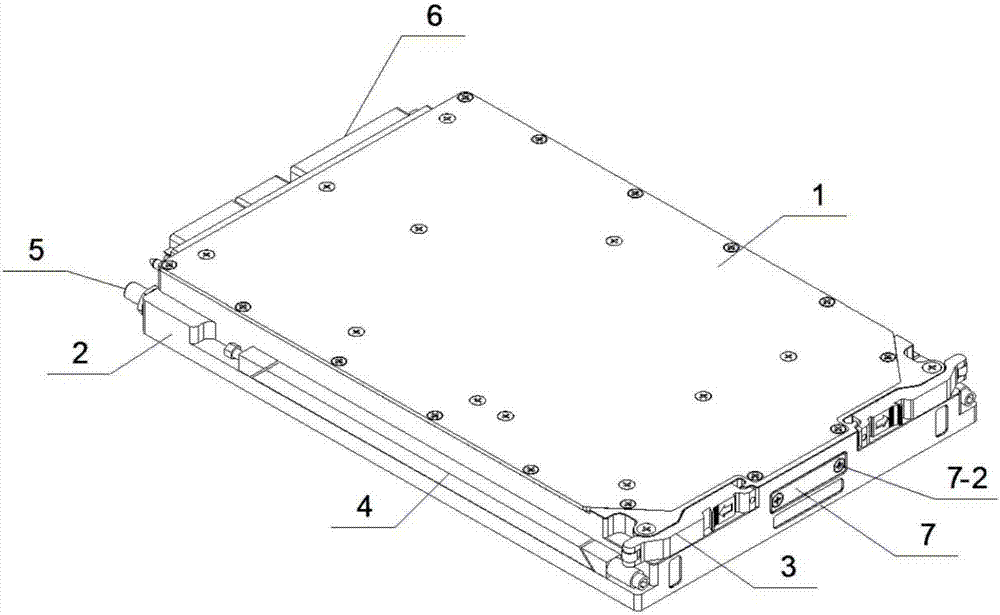
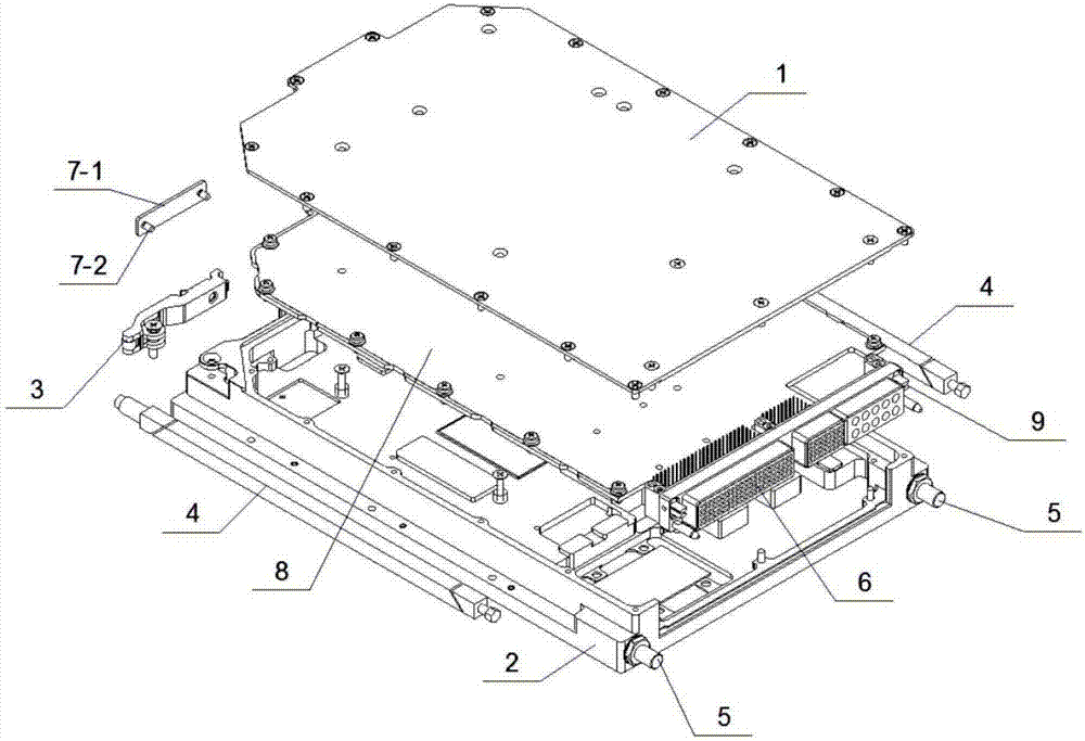
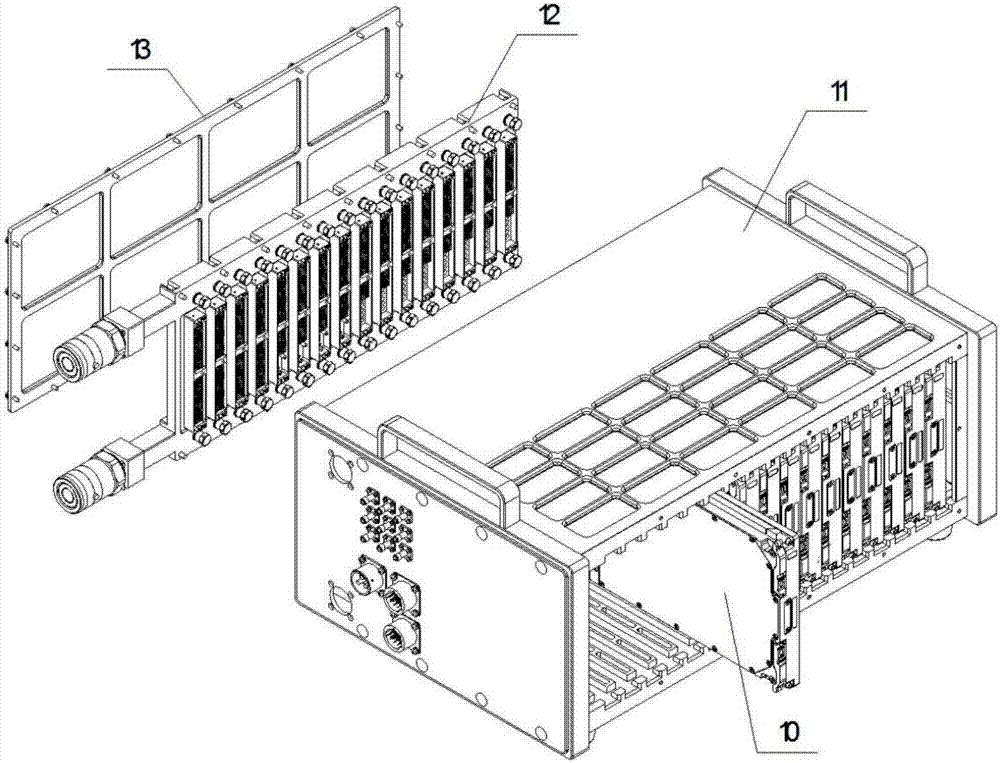
[0047] (1) If figure 1 , figure 2 , image 3 Shown is an embodiment of the present invention. In this embodiment, the functional module is transformed into a type that can realize fast plug-in and unplug capability, ultra-high heat dissipation capability, electromechanical-hydraulic collaborative blind plug capability, radio frequency blind plug capability, high electromagnetic shielding capability, Blind plug-in liquid cooling module with strong anti-vibration and shock ability, strong anti-salt spray ability, friendly man-machine interface, beautiful appearance, convenient operation and meeting the requirements of military environment.

[0048] The entire module adopts a modular design idea, and the cover plate 1, the puller 3, the locking ba...


PUM

PropertyMeasurementUnit
Section sizeaaaaaaaaaa
Thicknessaaaaaaaaaa

Abstract

A blind plug type liquid cooling module comprises a liquid cooling cavity which is composed of a cavity, a built-in flow channel, and fluid. A puller is arranged in the front of the liquid cooling cavity. A floating blind plug connector is arranged in the rear of the liquid cooling cavity. A plurality of printed boards or devices are arranged in the middle. Locking strips are arranged at both sides. A cover plate is arranged at least above. The cover plate, the liquid cooling cavity and the floating blind plug connector constitute an isolated chamber which provides electromagnetic shielding and salt fog isolation for the printed boards or the devices. A blind plug liquid cooling joint is arranged in the rear of the liquid cooling cavity. A cooling channel is formed between the blind plug liquid cooling joint and the built-in flow channel of the liquid cooling cavity. Cooling liquid circulates in the cooling channel to cool the printed boards or the devices.

Description

technical field [0001] The invention relates to a blind plug-in liquid cooling module, in particular to a module that can provide fast plug-in and pull-out capabilities, ultra-high heat dissipation capabilities, electromechanical-hydraulic coordinated blind plug capabilities, radio frequency blind plug capabilities, high electromagnetic shielding capabilities, and vibration and impact resistance capabilities. It is a blind plug-in liquid flow function module with strong anti-salt spray ability, friendly man-machine interface, beautiful appearance, convenient operation and can meet the requirements of military environment. Background technique [0002] Because the function module is suitable for the requirements of the communication electronics industry, it meets the requirements of communication electronics function modularization, serialization and combination (three modernizations), and the size meets the relevant international and domestic standards. It is widely used in t...

Claims


Application Information

Patent Timeline
IPC IPC(8): H05K7/20
CPCH05K7/20272
Inventor 叶发亮
Owner 叶发亮
Learn More