Control system for all-digital single-pulse electroplating power supply

An all-digital, control system technology, applied in the direction of electrolysis process, electrolysis components, cells, etc., can solve the problems of low precision, limited range of parameter setting, increase of product cost, etc. Simple and reliable, good output waveform quality

Inactive Publication Date: 2013-12-11
KUNSHAN PUYUAN ELECTRONICS TECH
View PDF5 Cites 8 Cited by
  • Summary
  • Abstract
  • Description
  • Claims
  • Application Information

AI Technical Summary

Problems solved by technology

However, when the metal surface treatment process develops to the point where pulse power supply must be used to provide electrical energy, the disadvantages of this control mode that only uses a dedicated PWM chip are exposed.
First of all, since the only output state of a single pulse power supply has to be increased from the original 1 parameter (ie output voltage or output current) to at least 4 parameters (peak value, base value, peak pulse width, base pulse width) see figure 2 The schematic diagram of the output waveform of the pulsed power supply and image 3 The schematic diagram of the output waveform of the DC power supply shown in the figure is determined. The implementation of the analog circuit is more complicated and the accuracy is lower; secondly, due to the requirements of the metal surface treatment process, the accuracy of the pulse width has reached the 100 microsecond error level, and only the analog circuit is used. It is unrealistic to realize the circuit, because the aging of components cannot be overcome by the current technology, especially in the capacitor; again, in terms of the response characteristics of the control system, the analog circuit is the best control system due to its inalterability. The operating point can only work in the state of DC output or pulse output with fixed frequency, and for the case of variable frequency and duty cycle, the analog circuit cannot guarantee the optimal control in the entire digital output frequency domain range, resulting in pulse amplitude Accuracy drops
In addition, there are analog control circuits with relatively simple control methods. Most of them use comparators to realize PID control, and limited by the electrical characteristics of devices, the range of parameter setting is limited, and there are some metal surface treatment processes. It is difficult to integrate useful smart instruments and meters, etc. These are factors that restrict the development of pulse power supplies
[0003] In view of the above reasons, there are currently some digital control schemes in foreign countries. For example, the single-pulse power supply produced by Japan Sanshe Company uses a processor + analog control circuit scheme, which basically solves the various problems raised above. The effect is also very ideal, but there are still several problems: first, the coexistence of two sets of digital and analog control systems increases the cost of the product, reduces reliability to a certain extent, and increases the burden of maintenance and debugging; Second, due to the influence of the components in the analog control, the pulse output is limited to achieve the optimal control response in the full frequency range. The final performance is that the low-frequency part has an ideal waveform and the high-frequency part has too much overshoot. See Figure 4

Method used


Image

  • Control system for all-digital single-pulse electroplating power supply
  • Control system for all-digital single-pulse electroplating power supply
  • Control system for all-digital single-pulse electroplating power supply

Examples


Embodiment Construction

[0019] In order to make the object, technical solution and advantages of the present invention clearer, the present invention will be further described in detail below in conjunction with the accompanying drawings and examples. However, the examples given are not intended to limit the present invention.

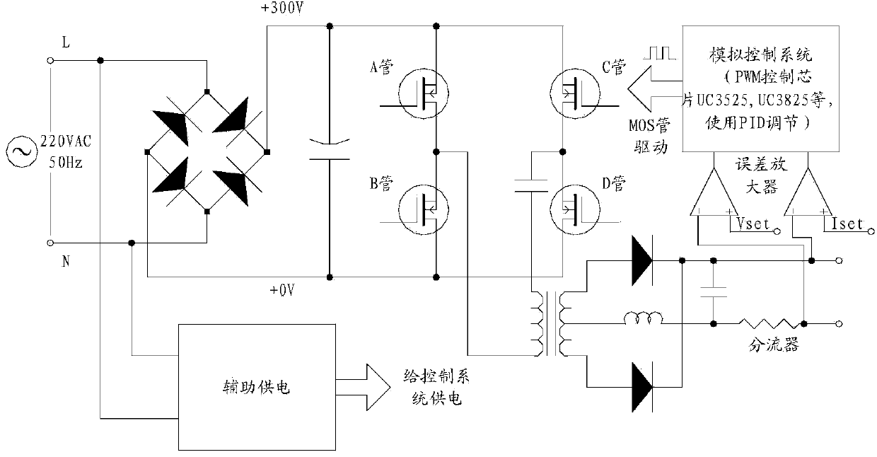
[0020] like Figure 5 As shown, the present invention provides a schematic structural diagram of a control system for an all-digital single-pulse electroplating power supply, including an EEROM 102 connected to a digital signal processing module 101 for storing power supply operating parameters and saving control parameters when power-off, a power board, and a secondary Level temperature detection and protection module 103, communication port 104 for completing communication, analog amplifier 105 for amplifying feedback voltage and telecommunication signal, PWM signal driving transformer 106, and power supply status indicator light and buzzer Display module 107.

[0021] A ...


PUM


Abstract

The invention provides a control system for an all-digital single-pulse electroplating power supply, and relates to the technical field of an electronic circuit. The control system comprises an EEROM (electrically erasable read-only memory), a power amplifier board, a secondary temperature detection and protective module, a communication port, an analog amplifier, a PWM (pulse width modulation) signal drive transformer and a display module, wherein the EEROM is connected with a digital signal processing module and used for storing the working parameters of the power supply and storing the control parameters in power failure, the communication port is used for completing communication, the analog amplifier is used for amplifying the feedback voltage and a telecommunication signal, and the display module is used for a power supply state indicator lamp and a buzzer. The control system for the all-digital single-pulse electroplating power supply is high in pulse width precision, and the consistency of products in the metal surface processing and the product quality can be guaranteed.

Description

technical field [0001] The invention relates to the technical field of electronic circuits, in particular to a control system for an all-digital single-pulse electroplating power supply. Background technique [0002] As the next-generation power supply equipment in the metal surface treatment process, single-pulse power supply has a good advantage over DC power supply, but at present, no matter whether it is DC power supply or single-pulse power supply, its control cannot lack the control part based on dedicated PWM chips, such as : UC3526, UC3825, etc. To a certain extent, this mode has its own advantages, especially in terms of reliability, which cannot be achieved by other modes in the switching power supply control mode, so that it occupies an absolute market share in the DC power supply, And continues to this day. For a typical control system scheme see figure 1 . But when the metal surface treatment process develops to the point that the pulse power supply must be ...

Claims


Application Information

Patent Timeline
Patent Type & Authority Applications(China)
IPC IPC(8): C25D5/18C25D21/12H02M9/06
Inventor 黄成柏
Owner KUNSHAN PUYUAN ELECTRONICS TECH
Why Eureka
Try Eureka